|
Input files
|
TwistedQuad.MIN, TwistedQuad.HIN
Download TwistedQuad.zip
|
|
Description
|
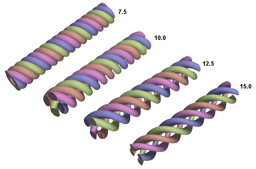
Electrostatic quadrupole arrays are effective for the transport of low energy ion beams. One application is a transport section between ion source and accelerator for differential pumping. A common configuration consists of discrete lenses of length L with 90° offsets to provide net focusing. A focusing cell has length 2.0*L. The top figure shows an interesting alternative, a twisted quadrupole array. It consists of four helical rods with applied voltages of altenating polarity. One full revolution (0.0 ≤ z ≤ Hw) is equivalent to two focusing cells (four effective lenses). The advantages are 1) an open structure favorable for pumping and 2) mechanical simplicity. Support and electrical connections need only be made at the ends.
This example covers mesh generation (MetaMesh) and the electrostatic solution (HiPhi). Other calculations addressing beam transport are listed under OmniTrak.
|
|
Results
|
An ideal quadrupole field can be generated with electrodes with hyperbolic cross sections. The example Optimized geometry for an electrostatic quadrupole with rod electrodes, shows that circular electrodes give a good approximation when the rods are displaced a distance of twice their radius R from the origin (in this case, the distance from the origin to the closest point on an electrode also equals R). The rod geometry is well matched to the MetaMesh HELIX model. The first task was a series of runs to determine practical values of Hw under the constraints. The top figure shows the resulting configuration displayed in Geometer for different values of Hw/R. Clearly, values Hw/R < 10.0 are too closely packed and would give a poor appoximation to a quadrupole field. For subsequent field and orbit calculations, the value Hw/R = 16.0 was used. Here, the effective lens length is twice the bore diameter.
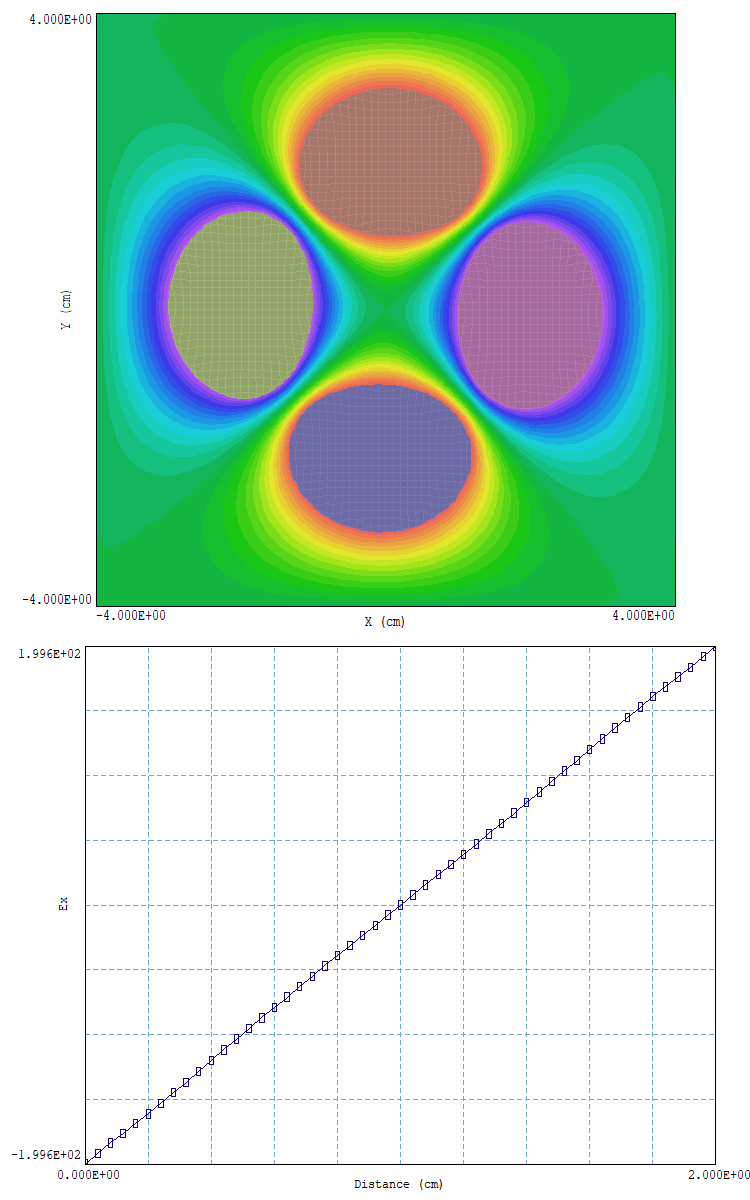
The mesh was used in a normalized HiPhi calculation with R = 1.0 cm and applied voltages of V0 = ± 1.0 V. For an ideal quadrupole, the predicted field magnitude on the electrode tip is E0 = 2.0*V0/R = 200.0 V/m. The calculation extended over three revolutions, 0.0 cm ≤ z ≤ 48.0 cm. The top section of the lower figure shows equipotential contours in the plane z = 24.0 cm where the electrodes are aligned with the axes. The bottom section is a field scan in the plane along x at y = 0.0 cm. The field is almost perfectly linear and the pole tip field is within 0.2% of the ideal quadrupole value.
|