|
Input files
|
MInduct.MIN, MInductL12.PIN, MInductL12.SCR, MInductL21.PIN, MInductL21.SCR, MInductScan.BAT, MInductScan.MIN, MInductScan.PIN, MInductScan.SCR
MInduct_Loops.zip
|
|
Description
|
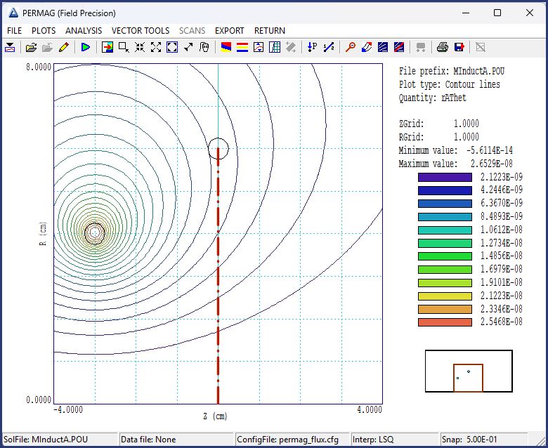
This example covers two techniques in PerMag: 1) calculating mutual inductance and 2) setting up automatic calculations for parameter searches. The top figure shows the template geometry. Concentric circular loops with 8.0 cm (Circuit 1) and 12.0 cm (Circuit 2) diameters were located inside a flux-encluding metal cylinder of diameter 24.0 cm. Both rods had 0.50 cm diameters and could carry 1.0 A current. Circuit 1 could be positioned at different axial locations.
In review, the following definitions apply to self and mutual inductance of two circuits:
- L11: Flux linkage in Circuit 1 divided by the current in Circuit 1
- L12: Flux linkage in Circuit 2 divided by the current in Circuit 1
- L21: Flux linkage in Circuit 1 divided by the current in Circuit 2
- L22: Flux linkage in Circuit 2 divided by the current in Circuit 2
Two calculations were performed to find the set of inductance values with Circuit 1 at z = 0.0 cm, designated MInductL12 and MInductL21. They used the mesh defined by MInduct.MIN. A third calculation (MInductScan) which determined L12 as a function of the axial position of Circuit1 used the mesh defined by MInductScan.MIN.
|
|
Results
|
Calculations and analyses for MInductL12 and MInductL21 were performed interactively, In the MInductL12 calculation, the current of Circuit 1 was equal to 1.0 A and the current of Circuit 2 was 0.0 A. The analysis script MInductL12.SCR had the content:
INPUT MInductL12.POU
OUTPUT MInductL12.DAT
CONFIGURATION C:\fieldp\tricomp\permag_flux.cfg
VOLUMEINT
NSCAN 100
LINEINT 0.0 0.0 0.0 6.0
NSCAN 20
SCAN 0.0 0.0 0.0 6.0
ENDFILE
The CONFIGURATION command ensured that the configuration for flux integrals was currently loaded. The VOLUMEINT command gave the field energy outside Circuit 1 as 6.2334E-8 J, implying a self inductance of L11 = 1.2467E-7 H. The line integral, taken along the path shown as a red line in the top figure, gave the value L12 = 5.8651E-8 H. The value was smaller than L11 because there are both positive and negative components of Bz in the plane (confirmed by the results of the SCAN command). For the MInductL21 calculation, 1.0 A is applied to Circuit 2 and the line integral in MInduct21.SCR was taken over the area enclosed by Circuit 1. The results were U = 1.1373E-7 J, L22 = 2.2746E-7 H and L21 = 5.9327E-8 H. We can make some comparisons with theory. The self-inductance of a thin loop is approximately
L = Mu0*(D/2)*[ln(8D/d) - 2].
Entering values for Circuit 2 gives 2.4627E-7 H. The predicted field at the loop center for an infinite surrounding space is
B = Mu0*I/D = 1.050E-5.
The SCAN operation gives the field r = 0.0 cm as 0.934E-5, with an average value over the interior of Circuit 1 of about 1.2E-5 T. The predicted mutual inductance is L21 = 1.2E-5*pi*0.04^2 = 6.0E-8. Finally, the mutual inductance values satisfy L12 ≅ L21, as predicted by theory.
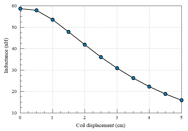
In the final calculation, the flux inside Loop 2 was calculated at eleven axial positions of Loop1. The operations ran in the background controlled by the Windows batch file MInductScan.BAT. The displacements were defined as pass parameters to Mesh. A magnetic field calculation and an analysis controlled by MInductScan.SCR was performed for each instance and recorded in a single data file MInductScan.DAT. The lower figure shows the results.
|
|
Comments
|
The example task_demo.html gives information about automatic operation under batch file control. Links to related examples:
Self inductance of a wire loop, low frequency
Self inductance of a wire loop at high frequency
3D inductance calculations with Magnum
|