|
Input files
|
LoopInductDC.MIN, LoopInductDC.PIN, LoopInductDC.png, LoopInductDC.SCR, permag_flux.cfg
LoopInductDC.zip
|
|
Description
|
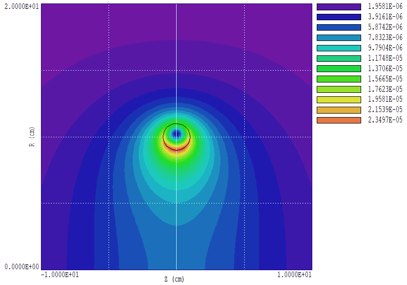
The example is the first in a series illustrating techniques for self and mutual inductance calculations with PerMag, Nelson and Magnum. This 2D PerMag calculation addresses the self-inductance of a simple current loop at low frequency. A special analysis configuration file was created for calculations of magnetic flux (Phi) through surfaces using the line integral function. Results are compared to those obtained from field energy volume integrals. This feature will be essential for following calculations of mutual inductances. The figure below, an r-z plot, shows the loop geometry and calculated values of |B|. The wire has diameter d = 2.0 cm and carries an azimuthal current I = 1.0 A. The loop diameter is D = 20.0 cm. The solution volume has large dimensions (50 cm) and a flux-excluding boundary to approximate infinite space. The familiar formula for the inductance of a thin loop is
L = Mu0*(D/2)*[ln(8D/d) - 2].
For the given parameters, the predicted value is L = 2.994E-7 H.
|
|
Results
|
A volume integral of field energy U gives accurate results for the self-inductance following the equation U = L*I^2/2. PerMag calculates the values U(air) =1.477199E-07 J and U(loop) = 1.664743E-08 J. The inductance formula above applies to magnetic energy in the vacuum region, with the assumption that the frequency is high enough so that the current flows in a thin layer on the wire surface (no field energy inside the wire). Multiplying the air result by 2.0 gives L(pred) = 2.954E-7 H, within 1.3% of the analytic estimate.
The configuration file permag_flux.cfg contains the standard plot functions and the field energy in the VOLUME section. The SURFACE section, used to define quantities for surface and line integrals, contains the entry
Phi = &Bxz;&Byr,
the vector components of the magnetic flux density. The surface integral function of PerMag is not useful because all magnetic flux that enters one surface of a region must leave by another surface. Instead, the line integral method is used. The normal and parallel components of the vector quantity relative to line are calculated and multiplied by the line segment length for solutions with rectangular symmetry. The factor for cylindrical solutions is the segment length multiple by 2*pi*r. Therefore, the normal component of the quantity Phi is the magnetic flux through the surface defined by the line. The self inductance of the loop equals the flux divided by the drive current. In the case of a 1.0 A drive, the flux is numerically equal to the inductance. The analysis script LoopInductDC.SCR has the content:
INPUT LoopInductDC.POU
OUTPUT LoopInductDC.DAT
NSCAN 200
VOLUMEINT
LINEINT 0.0 0.0 0.0 9.0
LINEINT 50.0 10.0 1.0 10.0
LINEINT -50.0 10.0 -1.0 10.0
ENDFILE
The VOLUMEINT command gives the result mentioned above. There are three LINEINT calculations on surfaces extending from the solution boundaries to the wire surface at different locations. The three paths give values 2.7654E-7, 2.9838E-7 and 2.9856E-7 H. The small discrepancy on path to the axis results from the strong field gradient near the inner wire surface.
The predicted flux density at the loop center is
B = Mu0*I/D
Inserting values for the current geometry, we find that 6.285E-6 T. The PerMag result is 6.2459E-6 T, a difference of 0.6%.
|
|
Comments
|
In PerMag, the applied current density in a region is uniform. If the current in the wire were limited by resistance, we might expect slightly higher current density near the inner radius. The PerMag condition would be a good fit to a loop consisting of multiple wires with uniform packing density. With a number N wires in the cross section, the calculated inductance should be multiplied by N^2.
Links to related examples:
Self inductance of a wire loop at high frequency
3D inductance calculations with Magnum
|