|
Input files
|
MInductEnergy.BAT,MInductEnergy2D.MIN, MInductEnergy2D.PIN, MInductEnergy2D.SCR, MInductEnergy2D1.PIN, MInductEnergy2D12.PIN, MInductEnergy2D2.PIN, MInductFluxCheck.SCR
Induct_Energy.zip
|
|
Description
|
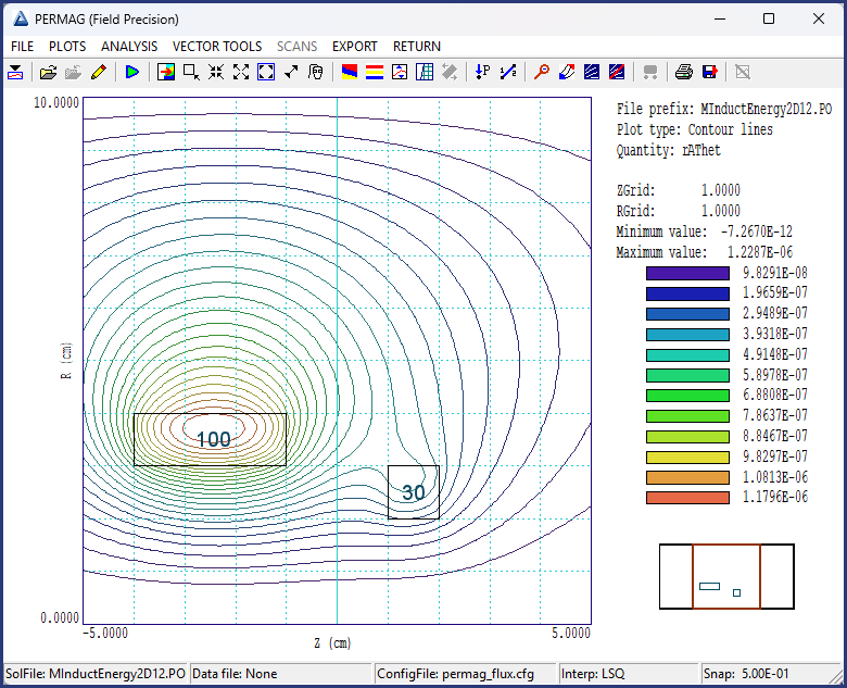
Direct flux integrals are informative for simple geometries like the single-turn loops in the examples mutual_inductance.html and loop_inductance_3D.html. The approach is impractical for inductance calculations involving extended multi-turn coils. An accurate calculation for a long coil with 250 turns could involve the sum of flux integrals over 250 planes. Fortunately, the energy method is an effective alternative for numerical solutions. It provides high accuracy and is easy to implement. Chapter 14 of the Magnum manual reviews the theory. This example illustrates how to find the self and mutual inductances of the geometry shown in the figure, two solenoid coils inside a cylindrical enclosure. An assumption is that the coils shown have uniform winding density with the number of turns shown. The goal is to find the self-inductances of each coil (L11 and L22) and the mutual inductances (M12 = M21). In the discussion, the 30-turn winding is designated Coil1 and the 100-turn winding as Coil2.
|
|
Results
|
For a two-coil system, the energy method involves a calculation exciting Coil1 with an input current of 1.0 A with no current in Coil2 to yield a field energy U10. Two additional calculations are performed with current 1.0 A in Coil2 to yield energy U01 and with current 1.0 A in both coils to yield energy U11. In all cases, the regions of the air coils have MuR = 1.0. In the first PerMag calculation (MInductEnergy2D1.PIN), a total current of 30.0 A is assigned to the Coil1 region, representing 30 turns of 1.0 A. The second calculation (MInductEnergy2D2.PIN) has 100.0 A assigned to the Coil2 region (100 turns at 1.0 A). In the third calculation (MInductEnergy2D12.PIN), the coil regions have currents 30.0 A and 100.0 A respectively. Once the mesh has been generated from MInductEnergy2D.MIN, the field solutions are generated and a PerMag analysis is performed controlled by MInductEnergy2D.SCR with the content:
OUTPUT MInductEnergy2D.DAT
INPUT MInductEnergy2D1.POU
VOLUMEINT
INPUT MInductEnergy2D2.POU
VOLUMEINT
INPUT MInductEnergy2D12.POU
VOLUMEINT
ENDFILE
The numerical results are U10 = 2.5367E-05 J, U01 = 3.1728E-04 J and U11 = 3.6715E-04 J. For a 1.0 A drive current, the self inductance of Coil1 is L11 = 2.0*U10 = 5.0734E-5 H. Similarly, the self-inductance of Coil2 is 2.0*U01 = 6.3456E-4 H. The energy method gives the mutual inductances as
M12 = M21 = (2*U11 - L11 - L22)/2 = 1.9853E-5 H
To test the result, we can estimate M21 by exciting Coil2 with 1.0 A, taking a flux integral over the average area enclosed by Coil1 and multiplying the result by 30.0. The calculation is controlled by the script MInductFluxCheck.SCR with the content:
OUTPUT MInductFluxCheck.DAT
CONFIGURATION C:\fieldp\tricomp\permag_flux.cfg
INPUT MInductEnergy2D2.POU
NSCAN 100
LINEINT 1.5 0.0 1.5 2.5
ENDFILE
In the LINEINT command, 1.5 cm is the average axial position and 2.5 is about the average radius of the coil windings. The resulting flux is 8.0701E-7 tesla-m^2. Multiplying by 30.0 gives M21 = 2.421E-5 H, consistent with the numerically-exact value.
|