|
Input files
|
InductEnergy3D.MIN, InductEnergy3D1.CDF, InductEnergy3D1.GIN, InductEnergy3D12.CDF, InductEnergy3D12.GIN, InductEnergy3D2.CDF, InductEnergy3D2.GIN, M3DEnergyMethod.SCR, MInductEnergy3D.BAT
InductEnergy3D.zip
|
|
Description
|
This example duplicates the 2D PerMag calculation of self and mutual inducances in the example Energy method for inductance calculations. There are two goals:
- Review Magnum methods for representing solenoidal coils and flux-excluding boundaries.
- Confirm that both codes give the same answers and check the accuracy.
Two annular, colinear coils are located in a cylindrical metal enclosure of radius 10.0 cm and length 20.0 cm. The coils have the following parameters:
- Coil1. Inner radius: 2.0 cm, outer radius: 3.0 cm, length: 1.0 cm, average axial position: 1.5 cm, number of turns: 30.
- Coil2. Inner radius: 3.0 cm, outer radius: 4.0 cm, length: 3.0 cm, average axial position: -2.5 cm, number of turns: 100.
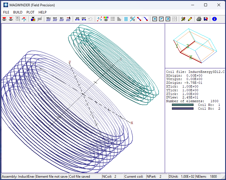
The Magnum calculation differs from the PerMag calculation in two ways: 1) assignment of drive currents in three dimensions and 2) definition of boundary conditions. More information is needed to define generalized 3D coils than for currents with 2D symmetry. The function of creating current elements in three dimensions is handled by MagWinder. The section of the MagWinder input file to represent Coil2 is:
COIL
  Name: COIL2
  Current:   1.0000E+02
  Shift:   0.0000E+00  0.0000E+00 -2.5000E+00
  Part
    Name: PART0002
    Type: Solenoid
    Fab:   3.0000E+00  4.0000E+00  3.0000E+00     3    10    40
  End
END
The SOLENOID model generates 30 circular filaments evenly spaced over the given dimensions. MagWinder sets the current in each filament for 100.0 A of circulating current (equivalent to 100 turns at 1.0 A). Filaments are divided into 40 azimuthal elements. The top figure shows both coils. The number of filaments and the azimuthal division affect the accuracy of the energy integrals.
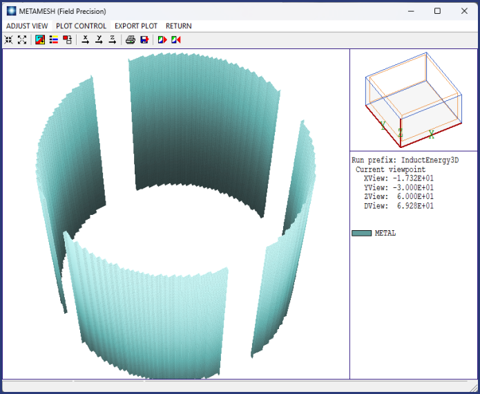
Flux exclusion is the natural boundary condition in Magnum. For an accurate comparison with PerMag, the solution volume should be cylindrical rather than the default box-shaped in Magnum. The procedure is to fill the solution volume with metal elements with a flux excluding property (MuR = 1.0E-5) and then to cut out a cylindrical air volume. The middle figure shows the result, the surface of the metal region. The unspecified surfaces assume the natural boundary condition.
|
|
Results
|
To employ the energy method, three calculations with the following drive current combinations are required:
- Run1: Coil1 = 1.0 A, Coil2 = 0.0 A,
- Run2, Coil1 = 0.0 A, Coil2 = 1.0 A,
- Run12: Coil1 = 1.0 A, Coil2 = 1.0 A.
There are several operations that can be performed in the background under the control of the batch file MInductEnergy3D.BAT:
START /B /WAIT C:\fieldp/amaze/metamesh.exe InductEnergy3D
START /B /WAIT C:\fieldp/amaze/magwinder.exe InductEnergy3D1
START /B /WAIT C:\fieldp/amaze/magwinder.exe InductEnergy3D2
START /B /WAIT C:\fieldp/amaze/magwinder.exe InductEnergy3D12
START /B /WAIT C:\fieldp/amaze/magnum.exe InductEnergy3D1
START /B /WAIT C:\fieldp/amaze/magnum.exe InductEnergy3D2
START /B /WAIT C:\fieldp/amaze/magnum.exe InductEnergy3D12
IF EXIST MInductEnergy3D.ACTIVE ERASE MInductEnergy3D.ACTIVE
Subsequently, the MagView script M3DEnergyMethod.SCR loads the three solutions and makes a volume integral of field energy over the air volume. The results yield the following inductance values using the relationships discussed in the 2D example: L11 = 5.0044E-5 H, L22 = 6.2575E-4 H, M12 = M21 = 1.9334E-5. The first two values are within 1.4% of the PerMag values. The mutual inductance value involves the difference of larger numbers and differs by 2.7%.
|
|
Comments
|
The generality of the 3D calculation offsets the extra effort involved in run preparation. It is easy handle non-colinear or tipped coils. Links to related examples:
Mutual inductance of circular loops
Self inductance of a wire loop, low frequency
Self inductance of a wire loop at high frequency
|