Many designs for electromagnets include a coil of the shape shown in Figure 1 wrapped around an iron mandrel with a rectangular cross section. The utility program Magwinder is used to define drive current elements for three dimension magnetic field calculations with the Field Precision Magnum program. In Magwinder, a coil box like Fig. 1 is constructed of four BAR type parts connected by four ELBOWR (elbow with a rectangular cross section) parts. The boxes must be rotated and translated from the their standard configurations to generate current in the correct position and direction, and the elbows must be shifted to the connecting positions. This involves some concentration and much busy work. Furthermore, the chances of error increase when there are multiple operations. In this article, I'll describe resources that I created to automate the process and review the plotting capabilities in Magwinder to check the results.
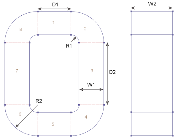
Figure 1. Definition of coil box parameters.
Figure 1 defines the geometric parameters of the coil box:
- The coil cross section has width W1 in the x-y plane and W2 in z.
- The coil is approximated by N1 current filaments in the x-y plane and N2 filaments in z.
- The BAR models have length D1 in x and D2 in y.
- The ELBOWR models have inner radius R1 and outer radius R2 and extend 90?.
- I is the total current carried by the filaments.
In the standard position, the current flows in the x-y plane in the counterclockwise when viewed from the +z direction. You can download the Magwinder sample input file coilbox_example.cdf which creates the structure for a specific set of parameters. The equations for the model parameters are listed as comment lines.
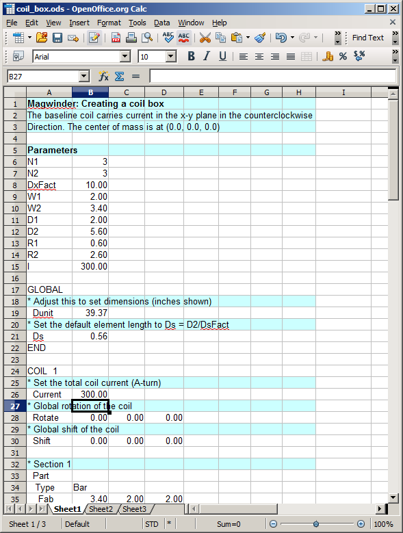
Figure 2. Spreadsheet for automatic calculation of coil box parameters.
I have also set up the spreadsheet shown in Fig. 2. To use it, fill in the parameter values and then copy and paste the cells starting at GLOBAL as text into a MagWinder script (CDF). Here is a link for a file for the Excel file (coil_box.xls).
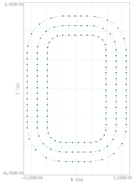
Figure 3. Resulting current elements with polarity indicators projected to the x-y plane (N1 = 3).
Figure 3 shows the resulting assembly projected in the x-y plane. The plot illustrates the new Magwinder capability to display the polarity of current elements. They are represented as sperm cells swimming in the direction of the head. There are two ways to reverse the current direction.
- Use a negative coil current, I → -I.
- Rotate the COIL 180° about the x or y axis.
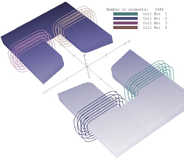
Figure 4. Quadrupole assembly with four coil boxes.
You can use the basic assembly multiple times in a Magwinder script. For example, Fig. 4 shows a quadrupole magnet. The standard text from the spreadsheet was pasted into four COIL sections, and then each coil was assigned a specific rotation and translation.
LINKS
