The programs Geometer and MetaMesh are used to build three-dimensional meshes for our multi-physics solution programs using constructive solid geometry. The user has the option to assemble objects from native models (e.g., spheres, cylinders, boxes, turnings,...) or to import complex shapes from SolidWorks and other 3D CAD programs. This article reviews how to make objects with conformal surfaces from native models. In particular, I want to clarify some points about conformal fitting.
To start, it's important to understand the concept of the initial foundation mesh versus the final conformal mesh. The foundation mesh is a regular, structured set of box elements that fill the solution volume. Regions in the solution volume are collections in elements that represent physical objects (such as electrodes and dielectrics in electrostatic solutions). In the volume-fitting process, the goal is to make an assignment of region numbers to the foundation-mesh elements for the best representation of the physical objects. The process of surface fitting occurs after the foundation mesh is complete. Here, elements on the object surfaces are shaped to follow the mathematical definitions of native parts or CAD models to produce the final conformal mesh. As a result, elements near the surface become generalized hexahedrons.
The two mesh-generation tools serve the following functions:
1) Geometer is an interactive, graphical environment to create or to edit parts in the foundation mesh. A part is a single native or CAD model. Objects may be composed of multiple parts. The output of Geometer is a text script that lists specifications of the foundation mesh and the included parts. The script (FName.MIN) acts as input to MetaMesh. A script may also be prepared directly with a text editor.
2) MetaMesh analyzes the script to produce a binary output file of the coordinates of mesh nodes and element identities used by the solution programs. If the user makes no changes to the script produced by Geometer, the MetaMesh output is a regular mesh of box elements, identical to the foundation mesh. The user adds or edits commands of the MetaMesh script to control conformal fitting. This process is the focus of this report.
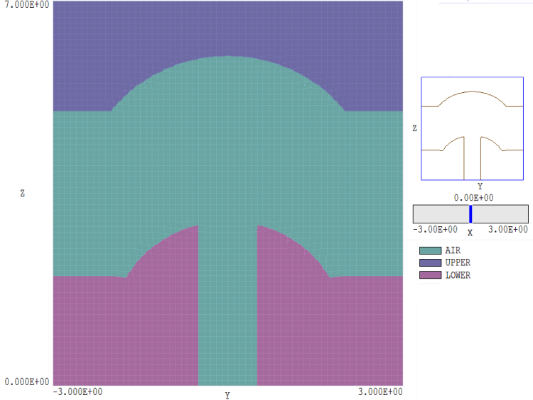
Figure 1. Example geometry.
Figure 1 shows the test geometry, a two-electrode gap. The solution volume covers the space -3.0 = x,y = 3.0, 0.0 = z = 7.0. The upper electrode has a spherical depression. The lower electrode has a spherical extension and a circular extraction port. The system has cylindrical symmetry about the z axis. A quick approach is to represent the upper and lower electrodes as turnings that extend beyond the boundaries of the solution volume. Instead, we will work with basic shapes to illustrate the construction procedure.
If we start a new script in Geometer with the given solution-volume dimensions, the program automatically adds a box region that fills the volume with the name SolutionVolume. Using the command to edit region names, we change the name of the first region to Air and the second and third region names to Upper and Lower. We then add a part with the name UpperElectrode and the region Upper. The part is a Box with dimensions Lx = Ly = 6.0 and Lz = 2.0 with a displacement 6.0 in z. To cut the depression, we add a sphere with name UpperCut, region Air, radius 2.5 and displacement 2.5 in z. The action changes the region identity of overlapped elements and nodes in the upper electrode to Air. Next we add a Box with name LowerElectrode, region Lower, dimensions Lx = Ly = 3.0 and Lz = 2.0 and displacement 1.0 in z to represent the lower electrode. The extension is a Sphere with name LowerExtension, region Lower, radius 2.0 and displacement z = 1.0. Finally, we add a Cylinder with name Aperture, region Air, radius 0.5, and length 7.0 to cut the hole. Figure 2 shows the resulting mesh created by MetaMesh if no changes are made to the script. It shows the familiar stair-step pattern for curved surfaces characteristic of regular meshes.
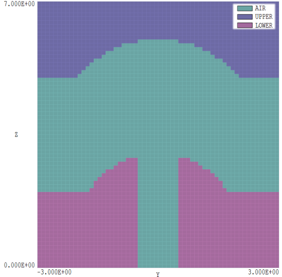
Figure 2. Mesh with no conformal fitting.
Before proceeding, we should note several significant points.
1) Some of the parts (like the Aperture) extended out of the solution volume. This is not a problem?? external sections of parts are ignored.
2) Regions may be created by the actions of multiple parts. For example, the lower electrode was the sum of the LowerElectrode and LowerExtension parts minus the Aperture part.
3) Note how the superposition principle affects the ordering of parts. For example, we enter the UpperElectrode and then cut then spherical depression by overwriting part of the object with Air elements. Only then do we then enter the LowerElectrode. If we entered both electrodes followed by the air sphere, both electrodes would have cuts.
4) Finally, there are special considerations for cutting holes when the mesh will be used in a solution program that depends on the node identity.
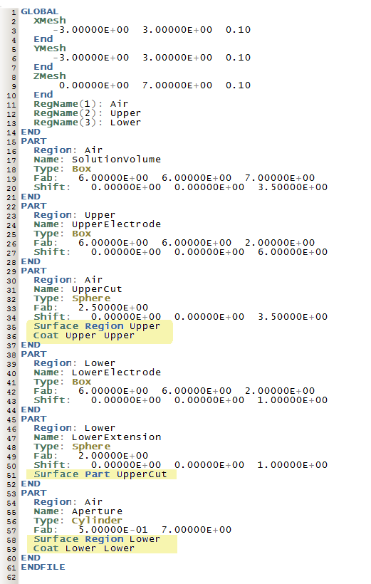
Figure 3. MetaMesh input script with fitting commands.
Figure 3 shows the input script produced by Geometer. The highlighted lines have been added to implement conformal fitting. The Global section (Lines 1-14) performs three functions: a) set the dimensions of the solution volume, b) specify the sizes of elements in the foundation mesh and c) define names for the regions. Part 1 (15-21) is the solution volume region defined by geometer with all elements set to region number 1 (Air). Part 2 (22-28) is the upper electrode that overwrites the air elements. Part 3 (29-37) is the spherical concavity in the upper electrode. In Part 3, the command
Surface Region Upper
states that elements of the part in contact with elements of type Upper should be shaped so that they conform to the spherical surface. The command
Coat Upper Upper
states that nodes shared with elements of region Upper should be marked as Upper. This operation ensures that the nodes of all elements in the upper electrode are marked as part of the fixed potential region. (Note: a valid solution is obtained even if we forget to add this command. Solution programs like HiPhi automatically set all nodes connected to fixed-potential electrodes to the fixed-potential region number.)
Moving on, Part 4 (38-44) is the lower electrode while Part 5 (45-52) is the spherical extension. The command
Surface Part UpperCut
states that elements adjacent to those marked as part UpperCut are shaped to lie on the spherical surface. The final part is the cylindrical aperture. The length of 7.0 ensures that the cylinder extends above the spherical extension while the section outside the solution volume is ignored. The commands
Surface Region Lower
Coat Lower Lower
move nodes shared with elements of the electrode to conform to the cylindrical shape and correct the region assignment of these nodes. Figure 4 shows a detail with nodes of the cylinder area.
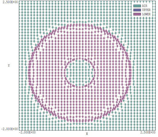
Figure 4. Detail of the mesh around the Aperture showing node assignments.
To conclude, I'll clarify why a Surface Part command is used in Part 4 rather than a Surface Region command. Fitting occurs after volume assignment operations (i.e., the foundation mesh has been completed). In this case, there are elements of with region identity Air in the aperture as well as in the gap between electrodes. Clearly, we do not want nodes inside the aperture to be shifted to the spherical surface of the extension. Such moves would cause severe distortion of the mesh. Therefore, we use a more specific designation to narrow down the set of nodes that should be shifted.
LINKS
