A issue often arises in electron gun design: for a given voltage, what is the highest possible beam current? By electron gun, I mean a conventional circular device. A sheet beam injector could extend without limit in the long direction and theoretically generate infinite current. Furthermore, I limit consideration to guns with an anode aperture rather than a grid. Gridded guns can achieve extremely high current, but the resulting beams can not be transported because of longitudinal space-charge effects. Furthermore, gridded guns are limited to very low duty cycle. Finally, I address non-relativistic injectors in the energy range ≤ 50 keV.
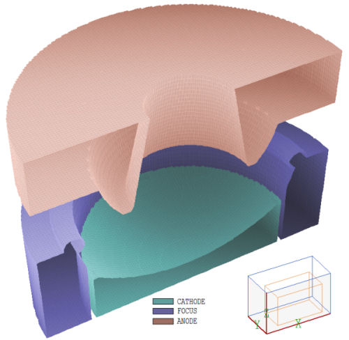
Figure 1. 3D view of the 3.2 uperv gun.
Sections 7.1 through 7.4 of my book Charged Particle Beams (available for download at https://www.fieldp.com/cpb.html) give a detailed discussion of the physical principles underlying high-current electron gun design. Here, I will summarize some of the main points. The maximum electron current density that can be accelerated across a planar gap of infinite transverse dimension is given by the Child law:
je = 2.33E-6 V03/2/d^2.
The units are A/m2 for d in m and A/cm2 for d in cm. An anode grid would be necessary to extract a beam from a uniform planar gap. Introducing an aperture of radius Ra eliminates a portion of the anode plane. There are two consequences if Ra is comparable to or larger than d:
- The reduced electric field near the cathode center lowers local current density and net current. Because the cathode temperature must be sufficient to supply the space-charge-limited current density at the edge, the source is used inefficiently.
- Nonlinear electrostatic focusing forces near the aperture edge lead to non-laminar orbits in the extracted beam.
If we impose the limit Ra ≤ d/2, then the extraction area is about A = πd^2 /4. Combining relationships, the maximum total current from an electron gun with an aperture is about
I ~ 2.33E-6 (π/4)\V0^3/2.
The perveance of an electron gun is defined as
P = I/V0^3/2.
The equation implies that the upper limit on perveance for a circular-beam gun is approximately P ≤ 1.9E-6 perv or 1.9 μperv. Higher perveance values may be achieved with a converging-beam gun. Here, a cathode surface with the shape of a spherical section produces a beam with reduced size at the anode, allowing a smaller aperture. The upper limit on perveance for a converging-beam gun depends on the tolerance to beam imperfections. The value is roughly 3 μperv.
In this article I'll describe a reference design for a 3.2 μperv electron gun. It is important to note the universality of the design. The scaling laws inherent in the electrostatic equations and the Child law mean that a single reference design can be applied to all possible non-relativistic electron guns. For example:
- To change the cathode diameter from Rc to Rc', multiply all dimensions by (Rc'/Rc).
- To change the current from Ie to Ie', adjust the voltage by (Ie'/Ie)^2/3.
- To lower the peak electric field by a factor (1/α), scale all dimensions by α.
My design has good (but not perfect) emitted current-density uniformity and an approximately laminar output beam. The peak electric field magnitude is low, the parts are easy to fabricate, the open structure allows good vacuum pumping and there is a relatively large gap between the cathode and focusing electrode.
The figures show the geometry. The specific instance has a cathode of radius Rc = 1.0 cm. The emission surface at r = 0.0 cm is located at axial position z = 0.0 cm. The applied voltage is 20 kV and the target current is 9.0 A. The cathode surface is a spherical section with center at position z = 1.6 Rc. The section encloses an angle of 38.7°. The focusing electrode (at the same potential as the cathode) serves two purposes:
- Reduction of field enhancement at the cathode edge to prevent enhanced current density.
- Shaping of global electric fields so that all electrons pass through the aperture.
The surface of the focusing electrode in a low-perveance gun is simply a conical section inclined at the Pierce angle (22.5°) with respect to the outer edge of the cathode. There is no set prescription for the electrode shape in a high-perveance gun. The focusing electrode shown was determined by informed trial-and-error. My goals were to maximum clearance between the beam envelope and the aperture edge, to achieve acceptable current-density uniformity and to generate an approximately laminar beam with a waist at the gun exit (z = 2.5 cm). Several iterations were necessary because an improvement of one characteristic tended to degrade the others. For example, increasing the aperture radius for more clearance reduced the emitted current density at the cathode center. A large extension of the focusing electrode to reduce current density on the cathode edge resulted in over-focusing of peripheral electrons. In the end, the design is a compromise, but a useful starting point. Note that the focusing electrode and anode form a simple planar gap at large radius. Modifications can be made to match to different mountings with a relatively small affect on fields in the gun region.
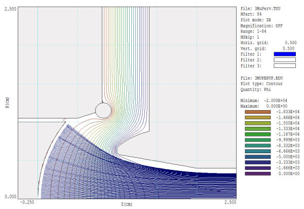
Figure 2. Self-consistent equipotential lines and model electron trajectories
Figure 2 shows model electron orbits in the self-consistent electric field determined with the Trak code. The emitted current is 9.0 A. There is about 0.7 mm clearance between the beam envelope and the anode extension. The beam reaches a waist of radius 3.5 mm at z = 2.4 cm. As a check, I confirmed that there was little difference in a Trak solution with full relativistic effects. A phase space plot of the extracted beam shows some over-focusing of peripheral electrons, giving an RMS angular divergence of 1.31°. The cathode current density was 2.0 A/cm2 at the center and 3.4 A/cm2 at the edge. The peak electric field occurs at the tips of the anode and focusing electrode. The value is relatively low, 83 kV/cm. The peak space-charge potential in the extracted beam is -860 V, leading to an RMS energy spread of ±141 keV.
Download a complete report on the gun with additional illustrations: highpervgun.pdf.
LINKS
