Mesh (our 2D mesh generator) can initiate a vector drawing directly from a DXF file. My consulting customers often send assembly drawings in DXF format that encompass a larger region than is needed for a field or beam calculation. In this article, I'll show how to pick out an interior area and trim vectors so that they fit inside using the tools of the Mesh Drawing Editor. (In the following discussion, I'll refer to the full menu commands of the editor. Most of them are represented on the toolbar.)
To minimize effort, it's useful to do some initial work in your CAD program to prepare the DXF file:
- Remove as many unneeded or unsupported entities as possible (e.g. delete a layer that contains only text).
- Organize physical objects into layers with the names "1", "2", "3",.... In this case, entities will be assigned to corresponding regions when they are loaded into Mesh. All entities in other layers are assigned to the layout region (Reg 0), and it's be necessary to move them laboriously into the correct regions.
Run Mesh and pick the command File/Create script/DXF import, pick the prepared DXF file and choose whether the 2D system is planar or cylindrical. If there are many details and the drawing is cluttered, click Settings/Vertex display to remove the symbols at the ends of line and arc vectors. Use the Zoom window command to view the region of interest.
Next, we'll make a clipping box to define the boundaries of the reduced solution volume. Use Insert/Start next region to add a region and set it as the current one for new entities.Click on Insert/Add rectangle and use the mouse pointer or coordinate input to create a rectangle and to set the desired solution-volume dimensions (Fig. 1).
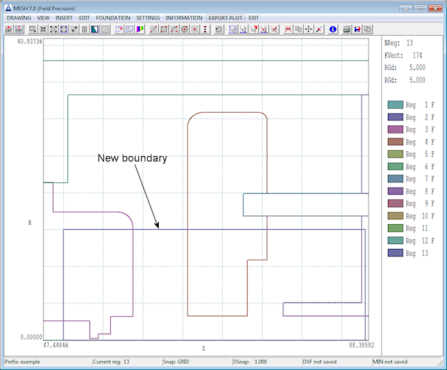
Figure 1. Original assembly from a DXF file with a clipping box.
Now expand the field of view to the full drawing (View/Global view). Use the Select/Window command to select vectors external to the clipping box and remove them with Edit/Delete selection. Repeat as many times as necessary to remove all objects that do not penetrate the new solution volume. When you are finished, the drawing should look like Fig. 2a. Next, use the Edit/trim vectors command to trim any vectors that extend out of the new solution volume. Click the command and set one side of the solution volume rectangle as the trim line. Then, click the endpoints of all vectors that penetrate the line. Finally, it is necessary to complete the outlines of any filled regions that extended outside the solution volume (Fig. 2b). Use the Information/Vector command to identify the region number of an object. Set that region as the current one (Insert/Set current region). Set the snap type to Endpoint (Settings/Snap control). Then use Insert/Add line to complete the outlines on the boundary. You can check that the outlines are complete with the View/Toggle fill display command.
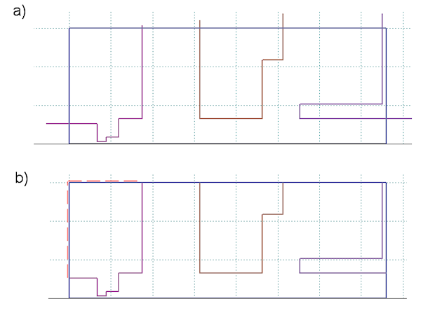
igure 2. a) After removal of all vectors with no portion inside the solution volume. b) Trim protruding vectors and complete the outlines along the solution volume boundary.
All this point, the drawing is correct but there may be several regions defined in the original DXF that have been completely removed. You can check with the Settings/Region properties command. The dialog (Fig. 3a) shows a list of regions, several of which have no vectors. Make a list of the regions to be removed, and click Settings/Region order. In the dialog (Fig. 3b), check the vestigial regions one by one (starting at the bottom of the list) and remove them with the Delete button. The final entry in the list of remaining regions is the outline of the new solution volume. Usually, this region should come first in the Mesh script to define the background medium (e.g., air or vacuum). Check the box for this region and press the Move up button multiple times to put it at the top of the list. Before saving the script, we need to adjust the dimensions of the drawing to correspond to those of the new solution volume. Click on Drawing/Change drawing limits to bring up the dialog of Fig. 4a. Note that the default dimensions already correspond to the new solution volume. The Drawing Editor checked the endpoints of all remaining vectors to set the limits. Click OK. Finally, save the results as a Mesh script (File/Export MIN file). Exit the Drawing Editor and check the results (File/Load/Script (MIN) and Process). Figure 4b shows the resulting mesh for the example with default element sizes.
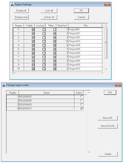
Figure 3. a) Dialog to set region properties showing the number of vectors. b) Dialog to delete regions and to change the region order.
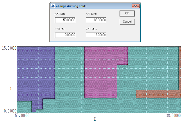
Figure 4. a) Dialog to set the solution volume limits. b) Processed mesh for the example.
On the topic of free CAD programs compatible with Mesh, I recommend LibreCAD, an open-source program that's sufficient for the task.
LINKS
