There are occasions in OmniTrak simulations when charged particles should pass through fixed potential surfaces. One example is the passage of high-energy electrons through a thin foil. Another example suggested by a customer are trajectories in the vicinity of the plasma column of a cyclotron ion source. Here, the plasma acts as a fixed-potential volumetric body transparent to recirculating ions. The main affect of the plasma is to distort the macroscopic electric field resulting in ion deflections.
To understand transparent electrodes, we need to review some features of electric-field solutions and particle tracking in HiPhi and OmniTrak. The mesh created by MetaMesh consists of hexahedron elements, small divisions of the volume. Nodes are the vertices of the hexahedrons. In MetaMesh, region numbers are assigned to both the elements and nodes. The solution of Poisson's equation involves determining electrostatic potential values at the nodes, influenced by the assigned of dielectric constant to the elements. Nodes inside and on the surface of an electrode are assigned a value that remains unchanged during the HiPhi solution process. Therefore, the region identity of elements inside the electrode does not affect the field solution. During particle tracking, OmniTrak stops a particle if it enters a Material region. Because the nodes have no volume, the code checks the region identity of elements. Therefore, if we constructed an electrode where the region number of nodes had the Material property but the region number of elements had the Vacuum property, then 1) the electric-field solution would be correct, and 2) particles would pass through without stopping. We can create such a region using the Coat command in MetaMesh.
Figure 1 shows an example solution, SOLIDDEMO. Protons accelerate across the Dee gap of a cyclotron with a cylindrical plasma column on the downstream side. Excerpts from the MetaMesh input file are listed at the end of the article. The solution includes the following regions:
RegName(1): Vacuum
RegName(2): Upstream
RegName(3): Downstream
RegName(4): Plasma
Region 1 is the standard vacuum propagation region, treated as a dielectric in HiPhi with??r = 1.0. Regions 2 and 3 are the fixed-potential electrodes. The important step is to assign a unique region number to the elements of the plasma column, even though they have the same physical property as the vacuum elements. MetaMesh uses this region number to identify nodes on the surface of the plasma.
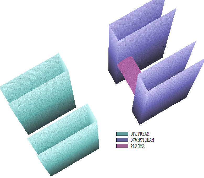
Figure 1. Geometry of the SOLIDDEMO example.
The Part sections to define solution volume and electrodes are unexceptional. The Part section for the plasma is the interesting one:
PART
  Region: Plasma
  Name: Plasma
  Type: Cylinder
  Shift: 2.00000E+00 0.00000E+00 0.00000E+00
  Rotate: 90.00 0.00 0.00 XYZ
  Surface Region Vacuum
  Coat Vacuum Downstream
END
The Surface command shapes facets on the boundary of the Plasma and Vacuum regions to conform to the cylindrical shape. The Coat command specifies that all nodes on the boundary between Plasma and Vacuum elements should be reassigned to the fixed-potential Downstream region. The plot of Figure 2 in a plane normal to the plasma column shows the assignment of nodes. This is exactly the condition that we want.
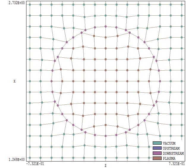
Figure 2. Assignment of nodes in the SOLIDDEMO example. Zoomed plot in a plane normal to the plasma column.
Figure 3 (a plot in the mid-plane normal to the plasma column) shows the distortion of fields resulting from the presence of the plasma along with sample orbits of 5 keV protons crossing the gap with an applied accelerating voltage of 10 kV. Similar techniques may be applied to 2D solutions with EStat and Trak. In this case, a fixed potential line region on the surface of the cylinder is created after the definition of the dielectric cylinder volume. For OmniTrak users, here is a link to download the input files for the SOLIDDEMO example: soliddemo.zip.
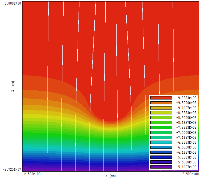
Figure 3. Electrostatic potential and particle orbits near the plasma column in the mid-plane normal to the column.
* File: SOLIDDEMO.MIN
GLOBAL
  XMesh
   -5.00000E+00 5.00000E+00 1.00000E-01
  End
  YMesh
   -5.00000E+00 5.00000E+00 1.00000E-01
  End
  ZMesh
   -5.00000E+00 5.00000E+00 1.00000E-01
  End
  RegName( 1): Vacuum
  RegName( 2): Upstream
  RegName( 3): Downstream
  RegName( 4): Plasma
END
PART
  Region: Vacuum
  Name: SolutionVolume
  Type: Box
  Fab: 1.00000E+01 1.00000E+01 1.00000E+01
END
PART
  Region: Upstream
  Name: ElectUpTop
  Type: Box
  Fab: 3.50000E+00 1.00000E+00 1.00000E+01
  Shift: -3.25000E+00 1.50000E+00 0.00000E+00
END
 ...
PART
  Region: Plasma
  Name: Plasma
  Type: Cylinder
  Fab: 5.00000E-01 2.00000E+00
  Shift: 2.00000E+00 0.00000E+00 0.00000E+00
  Rotate: 90.00 0.00 0.00 XYZ
  Surface Region Vacuum
  Coat Vacuum Downstream
END
ENDFILE
LINKS
