Sheet-beam electron injectors have long been used for industrial processing. Devices for such applications generally have a large cross-section area and relatively low-current density with minimal requirements on beam quality. Their development has been largely empirical. There has been considerable recent interest in sheet electron beams to drive innovative high-frequency, high-power microwave sources. These applications require tightly focused beams at current levels where electron dynamics is strongly influenced by space-charge effects. An extensive research effort on three-dimensional, space-charge-dominated injectors has resulted in sophisticated designs.
I this article I'll describe a simple way to create a high-quality sheet beam, so you can skip the three-year research program. The method produces elliptical beams with very high aspect ratio (i.e., Ry/Rx ≫ 1.0). It applies to space-charge-dominated beams in the limit of moderate to low perveance:
P = I/V^1.5 < 1.0E-6.
In the equation, I is the beam current in amperes and V is the injector potential in volts. The equation implies that the width of the acceleration gap d is large compared to the diameter of the beam.
To understand how the sheet-beam concept works, we need to review some basics of circular beam guns. Guidelines for designing moderate-perveance injectors for circular beams are discussed in Sects. 7.1 and 7.2 of my book Charged Particle Beams (Wiley-Interscience, New York, 1990). The book can be requested at https://www.fieldp.com/cpb.html. The strategy is to use a shaped cathode and focusing electrode to generate a beam that converges in the acceleration gap. The intent is to reduce the diameter of the anode extraction aperture, thereby minimizing its effect on gap electric fields. Transverse electric fields near the aperture defocus the beam. A circular aperture acts like a lens with negative focal length, given approximately by f = -4d. A derivation of the expression is given in Sect. 6.5 of my book Principles of Charged Particle Acceleration (Wiley, New York, 1986), available at http://www.fieldp.com/cpa.html. Depending on the degree of convergence in the gap, the beam extracted through the aperture may either diverge or converge.
Figure 1 shows a circular gun design (created with our two-dimensional Trak code) with parameters V = 20.0 kV, I = 0.46 A and P = 0.16 μperv. The cathode is a spherical section with 25.0 mm radius of curvature and 2.0 mm outer radius. The average current density is about 3.8 A/cm?. The focusing electrode shape was determined through trial-and-error adjustments to ensure 1) approximately uniform space-charge-limited current density over the cathode and 2) low emittance in the extracted beam. The electrode shape shown gives a parallel beam at the aperture exit. Errors in electron direction are less than 0.1°.
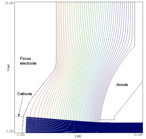
Figure 1. Model electron trajectories and electrostatic equipotential lines for a circular-beam injector, 0.16 microperv.
Given a circular injector design, the most straightforward approach to generate a line focus is to replace the circular aperture with a slot. There are two changes if the slot has an effectively infinite length in x:
- Transverse forces near in the aperture in the x direction are small.
- The forces in the y direction are doubled — the focal length of a slot aperture is approximately f = 2d.
The consequence is that the beam converges in the x direction and expands in the y direction. At the focal point in x, we expect to observe an approximately elliptical beam with Ry > Rx. The main issue is the limit on the minimum focal spot set by variations of applied and beam-generated electric fields.
We can apply the three-dimensional OmniTrak code to find a numerically exact solution. Figure 2 shows the geometry. The cathode, focusing electrode and anode are turnings with the same shape as those in the two-dimensional solution. The only difference is to cut a slot oriented along x of height 3.0 mm through the anode. The code gives a net current is 0.437 A, close to the two-dimensional result. As expected, the aperture shape has a relatively small effect in a low-perveance gun. The focus occurs at position z = 36.4 mm (relative to the cathode center).
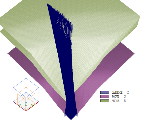
Figure 2. Three-dimensional view of one quadrant of the circular-beam gun with slot extractor, showing selected particle orbits.
Figure 3 shows the critical data, the beam profile at the short-direction focal point. The profile is approximately elliptical. The long-direction envelope radius is Ry ≅ 3.4 mm while the short direction radius is only Rx ≅ 0.106 mm. The geometry produces a tight short-direction focus with a beam-spot aspect ratio Ry/Rx ≅ 32. At the short-direction focal point, the beam has a small angular spread in y with an envelope divergence angle of about 6°. The root-mean-squared angular divergence in the short direction is less than 1°. With regard to changing the aspect ratio and position of the focal spot, there are two free parameters:
- All dimensions may be scaled by a factor without changing the perveance.
- The convergence angle in the acceleration gap may be changed.
With regard to the second option, higher convergence moves the focal point closer to the aperture exit. At the same time, the envelope expansion angle in y is reduced. Therefore, convergence in the gun strongly affects Ry/Rx.
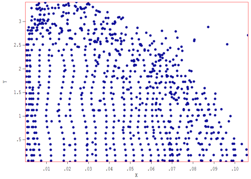
Figure 3. Distribution of model electron orbits in the x-y plane at a point 36.4 mm from the cathode center.
LINKS
