The standard method for building objects in MetaMesh is to piece them together from one or more parts. A part is a basic geometric shape defined by a parametric model (e.g., the radius and length of a cylinder, the side lengths of a box,...). Sometimes it's easy to make the shape you want, and sometimes it's not. That's why we included the capability of importing parts from 3D CAD programs like SolidWorks or ProE. There are some advantages to using the native models of MetaMesh, even if it takes some effort:
- You can tailor shapes to coordinate with mesh divisions.
- You can change parameters in?MetaMesh scripts with your own programs to create control loops and extended run sequences.
- If you're an infrequent 3D CAD user, you can avoid the anguish of relearning the program twice a year.
- Getting modified CAD shapes from your mechanical engineer can be time consuming.
- You only have to build a model once. After that, you can generate an infinite set of related shapes just by typing in a few numbers.
If that last point sounds interesting, read on. In this article, I'll show how to build a spreadsheet that can generate a entire class of shapes simply by changing parameters.
As an example, consider the rounded box of Fig. 1. The box has full widths of Wx, Wy and Wz along the axes of the fabrication space. The edges and corners have fillets of radius R. The top part shows a Geometer view of the box hanging on a rod with color-coding by parts. The following parts are required to construct the shape:
- 8 spheres of radius R shifted to the corners.
- 12 cylinders of radius R to define the edges with rotations and translations to position them.
- 6 boxes (slabs) to define the faces.
Looks like a lot of work. But remember, you only have to do it once!
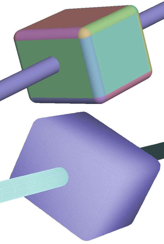
Figure 1. Rounded box model. Top: Geometer display of the component parts. Bottom: Finished mesh, output from MetaMesh.
The key is to use a spreadsheet to create MetaMesh script commands directly. Figure 2 shows my spreadsheet. Notice that comment lines start with an asterisk, following the MetaMesh script convention. The defining parameters are gathered at the top. To create the complete assembly, all you need do is set the four values. I also included the option of setting the region name of the assembly as well as that of the surrounding medium as strings in the parameter section. This information is copied to the REGION and SURFACE commands of all the parts. The content cells for the NAME command have entries like
=CONCATENATE($B$9;"DDD")
The highlighted cell in Fig. 2 shows typical information to set the required shifts and rotations to build the box. I won't attempt to describe the content of every cell. Rather, I'll give a link below so you can download the spreadsheet in Open Office Calc and Microsoft Excel format.
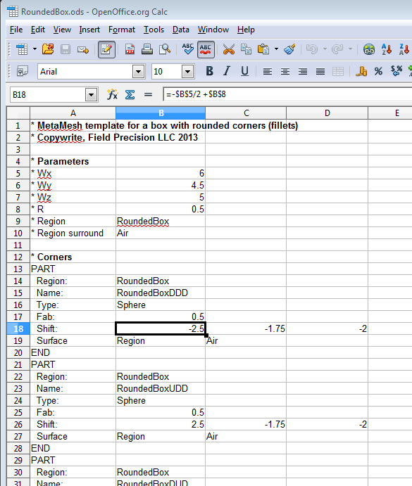
Figure 2. Initial section of the RoundedBox spreadsheet.
To add the part to a MetaMesh script, just copy and paste all the active cells of the spread sheet. This is where script directives come in handy. You can shift and rotate all 26 parts as a rigid body. Here's an excerpt from a test script:
#SHIFT 0.00 23.75 0.00
* Corners
PART
 Region: RoundedBox
 Name: RoundedBoxDDD
 Type: Sphere
 Fab: 0.5
 Shift: -2.5 -1.75 -2
 Surface Region Air
END
PART
 Region: RoundedBox
 Name: RoundedBoxUDD
 Type: Sphere
 Fab: 0.5
 ...
 Fab: 5 3.5 1
 Shift: 0 0 -2
 Surface Region Air
END
PART
 Region: RoundedBox
 Name: RoundedBoxZD
 Type: Box
 Fab: 5 3.5 1
 Shift: 0 0 2
 Surface Region Air
END
#ENDSHIFT
Here a link to zip file that contains the spreadsheets and the full MetaMesh script: RoundedBox.piz. Change the piz suffix to zip after you download it. Consider a standard parametric model whenever you find yourself building the same shapes multiple times.
LINKS
