Both our 2D and 3D mesh generators (Mesh and MetaMesh) must perform a critical task: identifying whether a point is inside complex closed boundaries defined by sets of line and arc vectors. The process is the core for assignment of elements to regions in Mesh. It is used in MetaMesh to assign elements to turnings and extrusions. Over the years, we have made considerable effort to ensure that the procedure is 100% accurate, an essential requirement when processing meshes of several million elements.
Nonetheless, we have observed an intermittent error that causes orphan elements isolated elements with an incorrectly-assigned region number. Figure 1 illustrates the phenomenon in a 2D mesh. The problem is not fatal in this case because orphan elements are easily identified and the Mesh program has mechanisms to correct such errors. On the other hand, orphan elements are a major issue in 3D meshes (Figure 2). It is impractical to seek out all errors in a large mesh and to correct them manually. Isolated elements corrupt the surface-fitting procedures in MetaMesh. The program interprets them as a part of the region surface, resulting in highly distorted meshes.
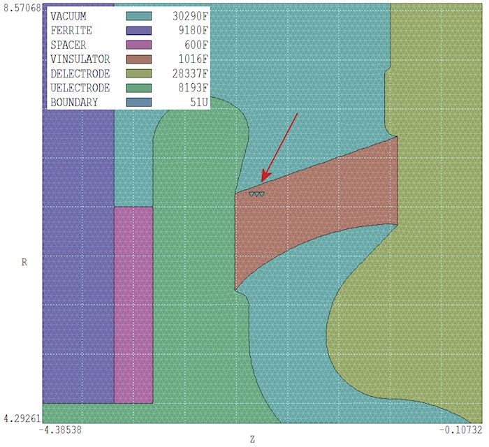
Figure 1. Orphan elements in a 2D mesh.
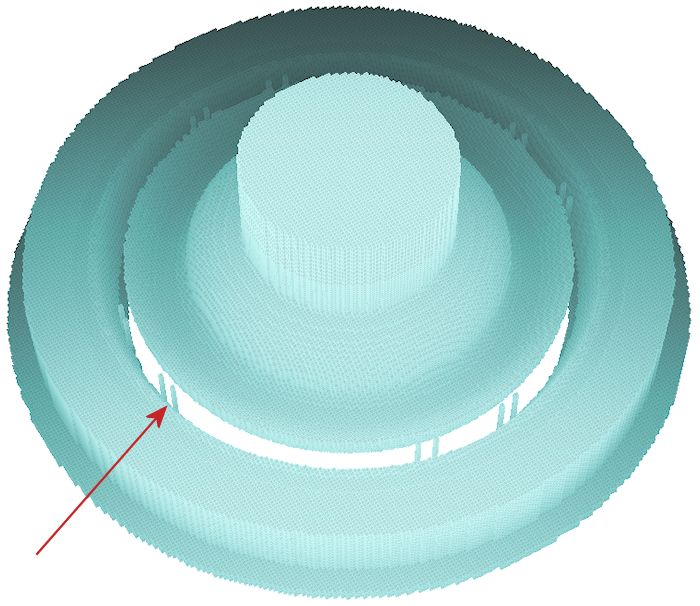
Figure 2. Orphan elements in a 3D mesh.
It is always difficult to identify the causes of rare, isolated events. Fortunately, a recent consulting project gave us the lead we needed to eliminate the error. Figures 1 and 2 illustrate the geometry, a complex acceleration cavity defined by a large set of boundary vectors with a shaped vacuum insulator. We were able to identify the two features of the calculation that lead to orphan elements:
- The boundary vectors were abstracted from a DXF file supplied by the customer.
- The meshes required a large number of small elements (3.6 million for the 3D case)
We checked mesh generation for each region of the solution volume. Surprisingly, there was no problem with the main cavity, although it had a complex boundary defined by 33 line and arc vectors. The errors occurred when the vacuum insulator was included. The region had the following specification:
PART
 Region: VInsulator
 Name: VInsulator
 Type: Turning
  L -2.38830 5.79000 -2.51603 5.64304
  L -2.51603 5.64304 -2.51603 6.63104<<
  L -2.51603 6.63504<< -0.93003 7.21754
  L -0.93003 7.21754 -0.93003 6.32654
  A -0.93003 6.32654 -2.38830 5.79000 -0.93003 4.07654
 End
END
I have added marks << to show the culprit inconsistent dimensions between the end point of one vector and the start point of another. The DXF file we received had an error. The difference is so small that it would be difficult to recognize in a graphical editor.
This insight explains the existence of orphan elements. MetaMesh determines if an element is inside a turning or extrusion by sighting outward and counting intersections with the boundary vectors. If there is a hole in the outline, the sight line may pass through without intersecting a vector. In this case, the element is assumed to be outside. Even though the hole may be very small, with millions of elements there is a good chance that some will be in position such that their sight lines intersect it. This explains the geometric regularity for the occurrence of orphan elements in Fig. 2. The reason we did not observe the error in many tests is because we normally use the Drawing Editor of Mesh or the Boundary Editor of MetaMesh in Snap mode to construct outlines, ensuring perfect connections.
2D and 3D mesh generation is flawless when the boundary vectors of the vacuum insulator are changed to:
  L -2.51603 5.64304 -2.51603 6.63104
  L -2.51603 6.63104 -0.93003 7.21754
We have made the following changes to Mesh, Geometer and MetaMesh to prevent errors:
- The tolerance for taking two floating-point numbers as equal has been tightened to 1/1000 of the width of the smallest element in the mesh.
- In the past, the programs checked only the beginning and end points of a closed set of boundary vectors for a match. Now, the programs check every connection and stop with an error message if there is a mismatch. The error message reports which vectors do not connect to help the user correct the values.
The good news is that our previous efforts to improve element identification have been worthwhile. With a perfectly-connected boundary, the process is highly reliable.
LINKS
