I often get questions about how to calculate capacitance using EStat or HiPhi. The main problem is that it is a derived quantity rather than one that pops directly out of the black box. In this note, I'll review a practical EStat calculation to show how to calculate mutual capacitances in a three electrode system. If you want to try the calculation, here are links to the input files:
http://www.fieldp.com/myblog/examples/capmonitor.min
http://www.fieldp.com/myblog/examples/capmonitor.ein
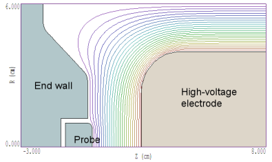
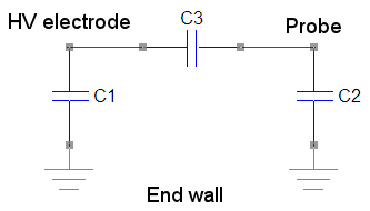
The first figure below shows a z-r plot of the geometry. The physical system is a figure of revolution about the bottom axis. The outer wall and the end wall are at ground potential. A pulsed voltage is applied to the electrode. The intervening space is filled with ethylene glycol (εr = 41.0). Part of the end wall (the probe) is isolated and connected to a measurement circuit. The intention is to use capacitive coupling to the probe to infer the voltage on the electrode. The second figure shows the equivalent circuit of the illustrated components. If we know the values of C1, C2 and C3, we can find the response of the measurement circuit to a pulsed voltage applied to the electrode node.
The most accurate way to determine the capacitances is to use the Volume integral command in the EStat analysis menu to calculate the global field energy. Suppose we run the following three solutions with different combinations of 1.0 V applied to the probe and electrode:
| V1(probe) |
V2(HV) |
Energy |
| 1.0 |
0.0 |
E1 = C2/2 + C3/2 |
| 0.0 |
1.0 |
E2 = C1/2 + C3/2 |
| 1.0 |
1.0 |
E3 = C1/2 + C2/2 |
The energy values come from the expression for the energy of a capacitor, CV2/2. We can solve the system of three linear equations in the last column to get expressions for the capacitance values in terms of the energies:
C1 = E3 + E2 - E1
C2 = E3 + E1 - E2
C3 = E1 + E2 - E3
Performing the solutions and taking the volume integrals, we find the following values for the energies: E1 = 1.1644 × 10⁻¹⁰ J, E2 = 2.0098 × 10⁻¹⁰ J and E3 = 3.1000 × 10⁻¹⁰ J. Inserting the numbers into the above equations, we find the following capacitance values:
C1 = 3.9454E-10 F
C2 = 2.2546E-10 F
C3 = 7.420E-12 F
If the probe is connected to a high-impedance measurement circuit, then the ratio of the probe voltage to that of the electrode is determine by capacitive division:
Vp/Ve = 1/C2/(1/C2 + 1/C3) = 0.03168
Everything looks straightforward, but its always easy to make a mistake. For example, one could solve the simultaneous equation incorrectly (which I did the first time). It's always a good idea to make a check. In this case, an inspection of the figure shows that electric field follows almost straight lines from the electrode to the probe. Therefore, we can make a good estimate of C3 from the familiar formula for a parallel-plate capacitor:
C3 = εr ε0 A/D
In this case, εr = 41 and D = 0.022 m. We need to estimate the effective area of the probe. It has a physical radius of 0.01 m, but it sticks out a bit and probably captures most of the field lines out to the inner radius of the end wall. Let's use R = 0.012 m, giving an effective area of 4.524 × 10⁻⁴ m2. Inserting values, we find that C3 = 7.46 × 10⁻¹² F, good enough for government work.
LINKS
