One of the major task in simulating three-dimensional electromagnets is the definition of complex drive coils. The utility MagWinder is part of the Magnum program suite. Drive circuits are represented in Magnum by dividing them into a large set of short segments (or current elements). MagWinder provides an interactive environment where users can build magnet windings step-by-step. Several features of MagWinder help in the task of current-element generation:
- A comprehensive set of parametric models for common coil configurations (solenoids, helices,...).
- Interactive dialogs to modify the geometry, position and orientation of components.
- Versatile graphical displays to show the state of the assembly.
Although the previous version of Magwinder featured high-quality 2D and 3D plots of coils, it did not have the provision to display objects in the finite-element mesh (iron pole pieces, permanent magnets,...). Such a display would allow users to confirm the size, orientation and placement of coil assemblies.
In response to user requests, we added a 3D mesh-display capability. Figure 1 shows the working environment of the new program. There are four associated commands (represented by new entries on the tool bar):
- Load a mesh definition file (MDF) created by MetaMesh
- Set the displayed mesh regions and the plot style. The region boundary facets may be shown as solid or as a wirefame. The boundary may be displayed as a continuum or as a set of facets.
- Set clipping planes for region facets
- Close the mesh file to display only the coils.
The interactive environment features the standard set of AMaze controls to move around in 3D space. Note that the plot shown in the figure has three-dimensional shading as well as hidden-line removal for both current elements and mesh object boundaries.
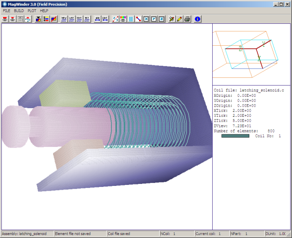
Figure 1. MagWinder working environment.
LINKS
