In our three-dimensional magnetic field code Magnum, electromagnets are driven by coil assemblies created with the MagWinder utility. A coil assembly is a large set of filamentary current elements to represent windings of any shape or degree of complexity. In previous versions of MagView, the superposition of current element information on standard mesh and facet plots was rudimentary. It was largely up the user to ensure that the geometries of coils and objects (like iron) were consistent.
In response to requests, we have upgraded coil/object plots in MagView to make them easier to understand and to enable quantitative checks on relative positions. Figure 1 shows a view in the slice plot menu. The intersections of current elements that penetrate the slice plane are shown as points. The color coding by coil number follows the convention of MagWinder. Users can zoom in on portions of the plot and use the grid display or coordinate mode to confirm the intersection points.
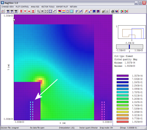
Figure 1. MagView slice plot menu with added display of coil intersections.
Figure 2 shows a view in the surface plot menu. Hidden line removal is now applied to the current elements as well as the facets that show the surfaces of objects and calculated quantities in a slice plane. We also increased the regeneration speed for coil plotting, added a tool in the main menu to load coils and added a new command to toggle quickly between perspective and orthographic views in the surface plot menu.
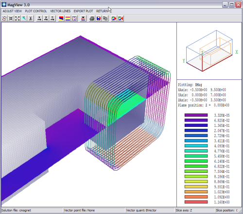
Figure 2. MagView surface plot with coils, complete hidden line removal.
LINKS
