Like many of these articles, this one was written in response to a user problem. In this case, the user found an issue in Mesh illustrated in Fig. 1. The mesh for a simple shape should look like the bottom illustration, but instead looks like the top one. The error was associated with the long arc vector along the top edge of the shape. The issue of long arcs is discussed in both the Mesh and MetaMesh manuals, but it is worthwhile to review it here.
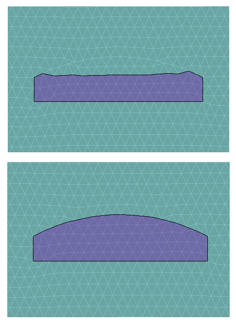
Figure 1. Meshing of a simple shape with a long arc surface. Top: Full arc. Bottom: Split arc.
In Mesh and MetaMesh, an outline is an arbitrary set of connect line or arc vectors to define a path or a shape. When the outline defines a shape (filled region), the vector set must close on itself. Outlines are used to define the boundaries of regions in Mesh and the cross-sections of turnings and extrusions in MetaMesh. There are two processing stages for outlines:
- The program moves nearby nodes (the vertices of triangular elements) so that they lie on the outline. This operation was performed correctly in both the top and bottom cases of Fig. 1.
- For filled regions, the program must determine if an element lies inside or outside a closed outline. The procedure may be challenging for complex shapes with a large number of vectors. In the top illustration, the identity of some elements has been assigned incorrectly.
Outlines may contain arcs with either positive and negative rotation. The issue is that the rotation sense of an arc specified by Start-End-Center is ambiguous. The convention in the codes is to pick the rotation direction that gives the shortest arc. Long arcs may cause confusion, as in Fig. 1. The solution is to ensure that all arcs in the outline do not exceed 90°. If the condition is satisfied, Mesh and MetaMesh always find the correct shape.
It is easy to fix long arcs in Mesh files with this procedure:
- Load the MIN file into Mesh.
- Click on Edit mesh (graphics) to enter the Drawing Editor (Fig. 2).
- Choose the command Edit/Split vector and use either the Midpoint or Nearest point options.
- Move the mouse cursor close to each long arc vector and left-click. The program splits the vector as shown and automatically reorders the vector list.
- Use the Export MIN file command to overwrite the existing file or to create one with a different name.
For the test case, splitting the arc at the midpoint gave the correct mesh on the bottom of Fig. 1. If you want to check this, here is a link to the Mesh input file for the long arc: longarc.min.
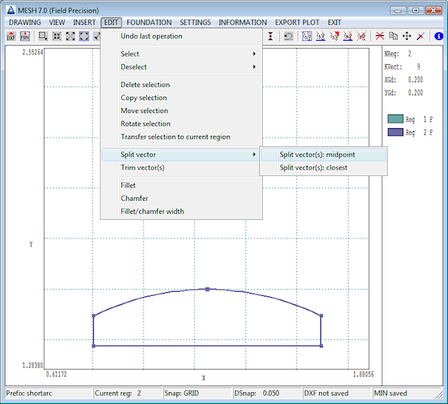
Figure 2. Screenshot of the Mesh Drawing Editor, splitting the arc vector.
LINKS
