Recently a customer asked about acceleration of an ion beam from a plasma. The goal was to generate a low-current beam from a plasma expanding into the acceleration gap through a small aperture. The issue is what is the optimal electrode geometries to produce a high-quality beam (lowest divergence)? In modeling electron extraction from a thermionic or field emission cathode, we can assume that the profile of the source surface is known. The challenge with plasma is that the surface shape is not fixed.
The Trak code has advanced capabilities to handle beam formation from a plasma. Sometimes users are not aware of the features or are uncertain of the implications of the model. In this article, I'll review 1) the basic physics of ion extraction, 2) how to design the best small aperture and 3) Trak features for large apertures. References are listed at the end of the article.
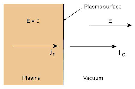
Figure 1. One-dimensional extraction of ions from a plasma.
A fundamental assumption is that the plasma has a free extraction surface. This means that the position of the surface is determined by a balance between the thermal flux of ions in the plasma (jp) and the flow of ions into the vacuum limited by space-charge effects (jc). The condition requires that magnetic fields near the surface are small. We'll begin with a one-dimensional extraction gap, with beam extraction along z and infinite extent in x and y (Fig. 1). The current density limit for ions with charge-state Zi and mass mi in a gap of width d and applied voltage V0 is given by the expression [1]
jc = (4*ε0/9) √(2*e*Zi/mi) V0^3/2/d^2.
If the ion flux exceeds the vacuum current limit (jp > jc), then the plasma expands to decrease the gap width d until a flux balance is achieved: jp = jc. In this case, the surface in Fig. 1 moves to the right. Conversely, if jp < jc, the surface recedes to the left. In most plasma sources for ion generation, the ion temperature (Ti) is much smaller than the electron temperature (Te). In this case, the available effective ion current density is given by the Bohm expression [2]:
jp ≅ 0.6*e*Zi*ni √(kTe/mi).
We'll assume that the plasma is homogeneous so that jp is uniform over the extraction surface.
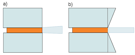
Figure 2. Ion extraction from a circular aperture. a) Missing space charge causes non-uniform emission and transverse deflection. b) Compensation with a Pierce electrode.
Next, we'll move to two-dimensional geometries: extraction from finite-width apertures (slot or circular hole). To be specific, consider a small circular aperture of radius R, where R ≪ d. Suppose the source is adjusted to provide a given flux jp and that we choose the gap width and voltage such that jc = jp. There is a problem if the electrode is flat as in Fig. 2a. In comparison to the infinite beam, there is missing space charge in the region region r > R. This means that there are transverse components of electric field. Also, the field magnitude is higher on the outer part of the emission surface. Because the flux is not balanced, this portion of the plasma recedes into the aperture giving the emission surface a complex shape. The result is a diverging ion beam. The solution is to shape the anode electrode to produce electric field components that replicate the contribution of the missing space charge (Fig. 2b). Following the derivation of J.R. Pierce [3], the electrode outside a slot should make an angle of 22.4? with the emission plane. For a circular aperture, the best angle is about 20.3° [4].
To review, here is the prescription.
- To start, we need to know the approximate flux jp available from the source.
- The choice of aperture radius R gives the target total beam current, Ib = jp*pi*R^2.
- For a given extractor voltage, choose the acceleration gap width d such that jc = jp. Include the appropriate Pierce angle on the anode electrode.
- To tune the system, adjust the plasma source power for a flux match (i.e., minimum beam divergence).
The problem is more challenging for a large aperture, where R ~ d (Fig. 3). In this case, the electric field may vary over the aperture so a numerical code like Trak is necessary. I'll give a brief summary of the procedure — a complete description is given in Ref. 5 and Chap. 13 of the Trak manual [6]. For a given electrode geometry and voltage, the goal is to find a surface in the region r ≥ R that ensures uniform space-charge-limited current density jc. The plasma source must supply a flux such that jp = jc. Where many users get confused is in asking the question, What if I turn the plasma flux up or down? The answer is, Don't do that! If jc is larger than a target value of jp, you need to change the geometry or the extraction voltage. Figure 3 illustrates how the shape is determined. An important factor is that the plasma surface is clamped to the triple point, the intersection of plasma, anode electrode and value (red dots). If the plasma receded into the aperture, the edge would be electrostatically shielded. With reduced field, the space-charge flux is small so the plasma expands back toward the triple point. Inversely, the electric field is strongly enhanced if the plasma sticks out past the triple point. With higher space-charge, the surface is eroded back. Figure 3a shows how to make a converging beam gun by increasing the angle of the focusing electrode. The shielding reduces the field on the periphery relative to the center. The higher flux at the center causes it to recede until the space-charge-limited current density equals the value on the periphery. Trak finds the unique surface by an iterative procedure. Inversely, the plasma bulges out if the electrode angle is reduced (Fig. 3b).
If you have questions or comments, please contact us at techinfo@fieldp.com.
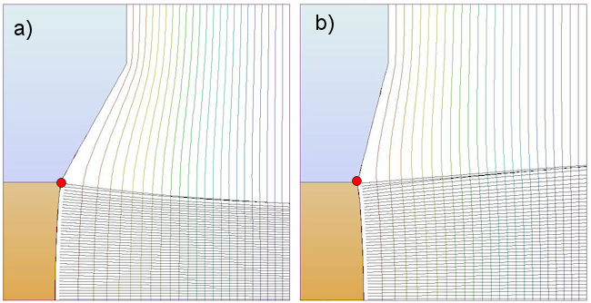
Figure 3. Ion extraction from a large circular aperture, Trak calculations. a) Increasing the angle of the focusing electrode gives a converging beam. b) Decreasing the angle of the focusing electrode gives a diverging beam.
References
1. C.D. Child, Phys. Rev. 32 (1911) 492.
2. See, for instance, S. Humphries, Charged Particle Beams, Sect 7.5 (Download: cpb.html).
3. J.R. Pierce, Theory and Design of Electron Beams (Van Nostrand, Princeton, 1949).
4. S. Humphries, Extended Pierce method for sheet-beam injector design (Download: sheetbeam.pdf)
5. S. Humphries, J. Comp. Phys. 204 (2005), 587 (Download: modeling_ion_extraction.pdf).
6. Trak Instruction Manual, Chap. 13 (Download: trak.pdf).
LINKS
