In the final installment, we will look at a 3D example of the calculation of mutual inductance. Discussions in this article have also been added to the Magnum manual (Chapter 13) You can download the latest version at
Library
The example illustrates the energy method described in a previous article applied to a two-circuit system, a high-voltage transformer consisting of primary and secondary windings on a toroidal ferrite core. The simple 3D geometry allows a comparison of numerical results to theory. Here are links to download the example input files:
inductdemo.min
inductdemo.cdf
inductdemo.gin
The core and windings have square cross sections with the following dimensions:
Core: ri = 4.00 cm, ro = 6.50 cm. h = 2.50
Primary winding: ri = 3.75 cm, ro = 6.75 cm. h = 3.00
Secondary winding: ri = 3.25 cm, ro = 7.25 cm. h = 4.00
In operation, the core has an average magnetic permeability of μr = 500
The windings have a relatively large number of turns for a good comparison with theory. We shall use the same number of turns of the primary and secondary windings (N1 = N2 = 72) and then scale the results. The figure below shows the set of 8064 current elements created by Magwinder from the file InductDemo.CDF. We have the option to set the drive currents for the two windings in the same or opposite directions. The choice determines the sign of M12, but does not affect the magnitude.
The example employs symmetry conditions to minimize the run time. The solution includes one-eighth of the system volume in the space x ≥ 0.0, y ≥ 0.0, z ≥ 0.0 with an element size of 0.1 cm. The planes at x = 0.0 and y = 0.0 are set as symmetry boundaries (B normal to the plane), while the boundary at z = 0.0 has the natural boundary condition (B parallel to the plane). To find the self-inductance of the primary, we set I1 = 1.0 A and I2 = 0.0 A in the CDF file, generate a current-element set, carry out field solution with Magnum and find the global field energy in MagView. The Magnum script InductDemo.GIN includes following two commands:
CheckIron = OFF
OmitIron
The first command was added after initial runs to deactivate a check of whether current elements passed through the core. The calculation is time-consuming for the large number of current elements. The second command suppresses the calculation of the dual potential Ψ. The core region connects two symmetry boundaries with Ψ = 0.0 with no intervening air gap. Therefore, the dual-potential calculation would yield the non-physical solution H = - grad Ψ = 0.0. Because there is no dual potential, the Reduced mode must be used for field calculations in MagView.
The primary inductance is calculated by taking I1 = 1.0 A and I2 = 0.0 A. With no ferrite core, the field energy for one-eighth of the system was 1.1043E-06 J. The total calculated field energy was 8.8344E-06 J, giving L11 = 1.7669E-05 H. For comparison, the inductance value predicted by the standard formula for a toroidal inductor is 1.8283E-05 H. When the high-? core is present, it encompasses almost all the magnetic field energy. To estimate the primary inductance, we use ?r = 500 and the dimensions of the core in the toroidal inductor formular. The result is L11 = 6.2922E-03 H, quite close to the value of L11 = 6.2694E-03 H calculated with Magnum.
With I1 = 0.0 A and I2 = 1.0 A, the secondary inductance is L22 = 3.2391E-05 H with no core and L22 = 6.2796E-03 H with the ferrite present. As expected, with a core L11 = L22 because the magnetic flux is concentrated in the ferrite. Applying the equation derived in the previous article, the calculated mutual inductance is M12 = 6.2672E-03, equal to L11 and L22}. The result is as expected since the core gives almost perfect flux coupling between primary and secondary windings. The code values for an air-core transformer are L11 = 1.7669E-05 H, L22 = 3.2391E-05 H and M12 = 1.8304E-05 H. If we put a voltage V2 on the secondary, the predicted open-circuit voltage on the primary is given by V1/V2 = M12/L22 = 0.565. This value is consistent with the ratio of the cross-section areas of the primary and secondary coils, 9/16 = 0.563. The following scaling relationships may be used to find inductances for the actual number of primary and second windings:
L11 ~ (N1/72)^2* L11,
L22 ~ (N2/72)^2*L22,
M12 ~ (N1/72)(N2/72)*M12.
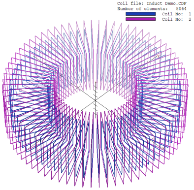
Primary and secondary coils for the transformer example.
LINKS
