The MetaMesh manual gives a complete explanation of the mesh generation process, but useful pieces of information may get lost because of the shear size of the document. In this post I'll review common sources of errors that account for most of the MetaMesh techhelp inquiries. The first two are simple while the third is more subtle, involving a clear understanding of logic of the meshing procedure.
Unfilled solution volume
The symptom is that the program stops with a message like "Empty element at X: 8.020E+00 Y: 1.020E-02 Z: 1.020E-02." The convention in MetaMesh is that all elements of the solution volume must have an assigned region number. In a typical solution, the first region is a box that fills the entire volume and represents vacuum or air. The error occurs when the user thinks that the box fills the solution volume but it doesn't. For example, suppose the solution has dimensions 0.0 ≤ x,y,z ≤ 10.0. The following specifications in the parts section will fill the volume:
Region: 1
Type: Box
Fab: 10.0  10.0  10.0
Shift: 5.0 5.0 5.0

Region: 1
Type: Box
Fab: 20.0  20.0  20.0
The second example uses the automatic clipping feature of MetaMesh. The following specification does not fill the solution volume:
Region: 1
Type: Box
Fab: 10.0  10.0  10.0
The resulting box would covers the region -5.0 ≤ x,y,z ≤ 5.0. The box model is describe in Sect. 8.1 of the MetaMesh manual.
Fitting turnings and extrusions
Suppose you define a turning or extrusion, including a statement like
Surface Region 4
and observe that the part has a stair-step boundary. Remember that you must also include the letter "S" at the end of the boundary vectors that should be fitted. Turnings and extrusions are discussed in Chap. 9 of the MetaMesh manual.
Holes and cavities
Two types of errors may occur when you drill holes or carve cavities in parts: 1) incorrect assignment of mesh nodes and 2) invalid fitting specifications that lead to mesh distortions. To illustrate, we will work through an example for an electrostatic solution: drilling a hole through a metal plate that occupies a portion of the air-filled solution volume. There are two regions (i.e., volumes where elements have the same physical properties): air (Region 1) and metal (Region 2). We construct the geometry from three parts, defined in the following order:
- Part 1. A box that fills the solution volume (Air).
- Part 2. A cylinder that defines the plate (Metal).
- Part 3. A smaller cylinder that passes through the plate to drill the hole (Air).
By the overwrite principle in MetaMesh, the plate replaces some of the air elements. This means that the elements and their associated notes are assigned RegNo = 2. Similarly, the hole returns some of the plate elements to RegNo = 1. Here's what can go wrong.
1) The nodes common to adjacent elements of the plate and the hole have RegNo = 1. For a valid electrostatic solution, these nodes must have the fixed-potential condition of the metal (RegNo = 2). The following statement must be included in the part definition of the hole:
Coat 2 2
All nodes of part elements common to RegNo = 2 will be assigned to the metal region.
2) If the statement
Surface Region 1
appears in the definition of the plate, the resulting mesh will be distorted. Figure 1 shows the distorted mesh that follows. This is because the statement tells MetaMesh to identify all facets of the plate that are adjacent to elements with RegNo = 1 and to try to fit them to the outer boundary of the plate. Clearly, trying to fit the inside of the hole to the outside of the plate will cause a mess. Here, is the correct statement:
Surface Part 1
This form ensures that only those facets that bound on the original solution volume elements will be fitted. Fitting the surface of the hole is done by including the following statement in its part definition:
Surface Region 2
If the procedure isn't clear, I have prepared an annotated example. Use these links to download the input files:
holedrill.min
holedrill.min
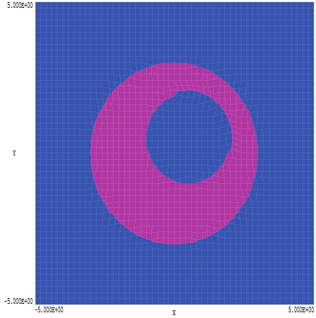
Figure 1. Drilling a hole with incorrect fitting specification.
LINKS
