In the previous article, I discussed the symbiosis between Mesh (our 2D mesh generator) and LibreCAD (an open-source 2D CAD program). There is an even closer relationship between MetaMesh (our 3D mesh generator) and FreeCAD, an open-source program for creating complex three-dimensional objects. Although you can achieve much with the constructive-solid-geometry operations applied in MetaMesh and the interactive Geometer preprocessor, the procedures may be difficult and time consuming when applied to a complex parts with curves, chamfers, fillets and other features. In these cases, it is often more efficient to create the part in FreeCAD and then to port it to MetaMesh as a stereo-lithography (STL) object.
FreeCAD has several advantages for this application compared to commercial packages like Pro Engineer, Solidworks, Inventor and AutoCAD.
- The outstanding advantage is that it is free and open (as opposed to costing thousands of dollars with strict license control).
- The available documentation is quite good.
- Its use of parts and their placement in coordinate systems is closely related to the logic of Geometer and MetaMesh.
- There are good resources for creating and exporting STL meshes.
- I found it relatively easy to learn following online tutorials.
With regard to the latter, there are some important concepts to master and several potential sources of confusion for new users. With that in mind, I thought it would be helpful to write a tutorial showing some basics of FreeCAD usage with tips on integration with Geometer and MetaMesh.
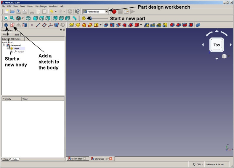
Figure 1. FreeCAD, starting a Part and adding a Body.
To begin, install and run FreeCAD. In the Start workbench, click on Create new... to open the display of Figure 1. To interact with MetaMesh, we are going to create a single part that will be exported as a stereo-lithograpy file. We need not worry about the location of the part in the FreeCAD coordinate space because we can adjust the position and orientation of the part in Geometer and Metamesh. Following Fig. 1, go to the Part design workbench and click the tool to start a new part. Click the Model tab on the left to see the organization. Right click on the Part and rename it Cathode.
Parts may include several Bodies joined together by logical operations. For this example, we'll need a single Body. Click the tool to add a Body to the current Part. The body will be a flattened pipe. As in Geometer, we make an Outline (Sketch) in a reference plane and then Extrude (Pad) it. Click the tool to start a Sketch. Choose x-y as the reference axis. FreeCAD switches to the Sketcher workbench (Figure 2), showing an appropriate set of tools. The information will be associated with the Body in the tree view on the left.
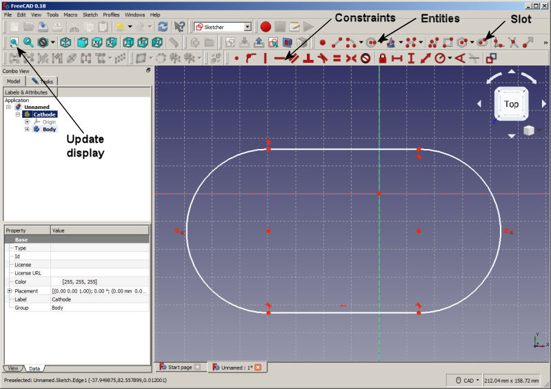
Figure 2. FreeCAD, creating on outline in the Sketcher workbench.
It is important to recognize that the sketching procedure in
FreeCAD differs from the standard method used in Geometer outlines and most 2D CAD programs. There is no grid-snap mode. Instead, the idea is to create a rough representation of the entity and then to apply constraints until it is fully defined. An example is the best way to see how this works. Click on the Slot model and use mouse clicks to create a slot of any size and position. Figure 2 shows the display. Points are shown as circles and the other red symbols are constraints. The default constraints for a slot have the following meanings: 1) the bottom line is horizontal, 2) the arcs and lines are tangential at the four meeting points and 3) the two arcs have the same radii.
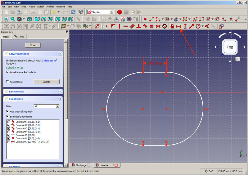
Figure 3. FreeCAD, adding a line length constraint in the Sketcher workbench.
We need to add constraints so that the sketch is specified unambiguously. Select the top horizontal line, click the horizontal length constraint and choose a value of 20.0 mm (Figure 3). Note the addition to the constraint list at the left. Now, select a top intersection point and hold down the control key to add a bottom intersection point to the selection. Then, apply a horizontal distance constraint (Figure 4) and specify the dimension 20 mm. Select 1) a left intersection point, 2) a right intersection point and 3) the vertical axis (green line) and then click on the symmetry constraint to center the shape in the coordinate system. Follow similar operations to place the shape symmetrically in the vertical direction. With this addition, the outline turns green, meaning that it is fully constrained (i.e., unambiguously defined). To complete the sketch, use similar operations to add the outer pipe wall as shown in Figure 5. Close the completed sketch.
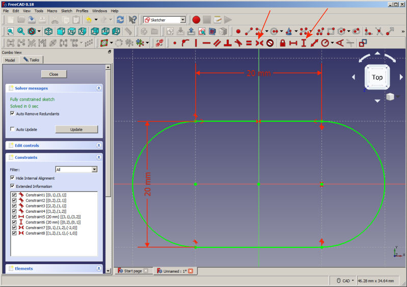
Figure 4. FreeCAD, fully constrained inner edge of the pipe.
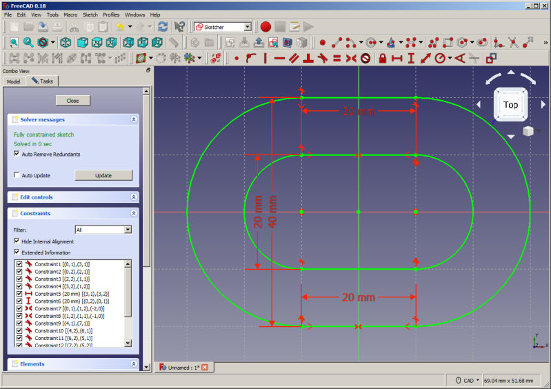
Figure 5. FreeCAD, completed sketch of the pipe.
Back in the Part design workbench, switch to an isometric view (Figure 6). The sketch outline is projected in the x-y plane. Click on the Pad tool and choose a value of 20.0 mm to create the solid body of Figure 6. Holding the control key, select the four vectors comprising the inner edge of the top face. Click on the Chamfer tool and specify a value 5.0 mm. Finally, select the vectors of the outer edge of the top face and add a 2.4 mm fillet. Figure 7 shows the final result. Save the work as Cathode.FCStd.
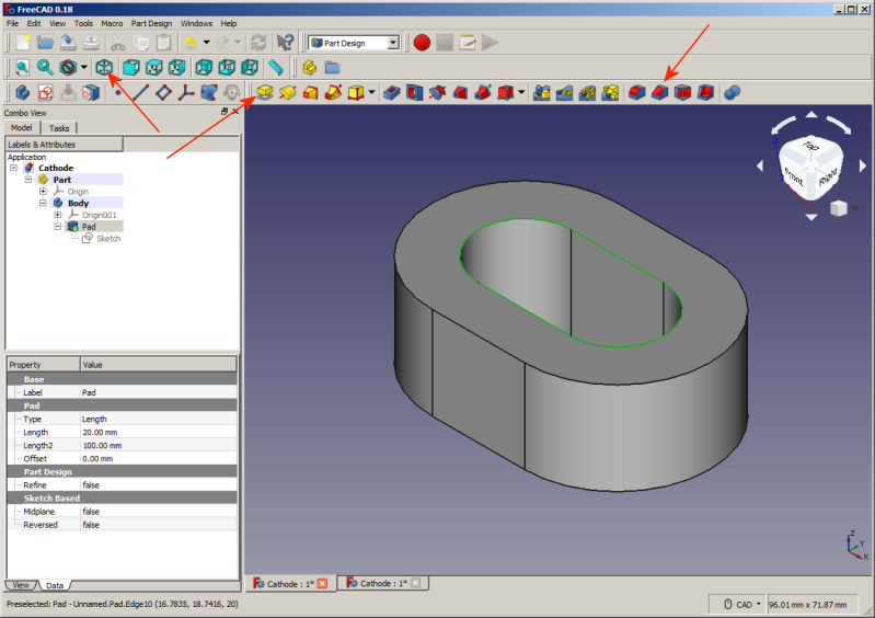
Figure 6. FreeCAD, extrusion of the sketch to create a pipe. Inner edge of top face selected.
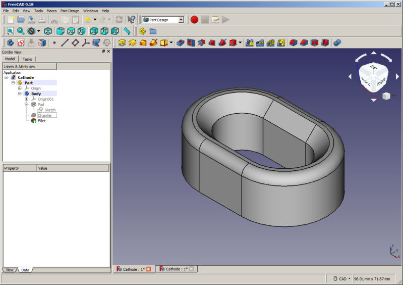
Figure 7. FreeCAD, addition of a chamfer and fillet to one end of the pipe.
The final step is to create a stereo lithography mesh to export to MetaMesh. FreeCAD can export these files in either binary (STL) or text (AST) format. For compatibility with Metamesh and Geometer, use the text format. You could export the current part directly, but the default mesh procedure makes poorly-formed, acute triangular facets. Instead, we will create a well-formed mesh of the body surface within FreeCAD and then export the result. Transfer to the Mesh design workbench. Select the body from the Model tree list on the left. From the menu at the top, choose Meshes/Create mesh from shape to display the options shown in Figure 8. Pick NetGen/Fine and click OK. Figure 9 shows the resulting well-formed mesh. Select Body (meshed) from the tree list and then choose File/Export from the menu. Choose the option STL mesh and give it the name Cathode.AST to signal text format.
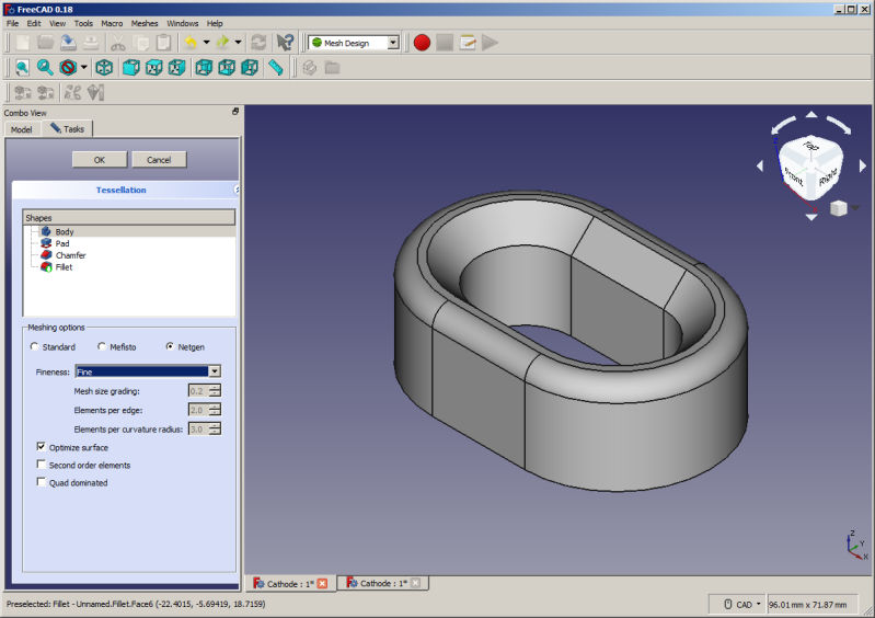
Figure 8. FreeCAD, mesh creation options.
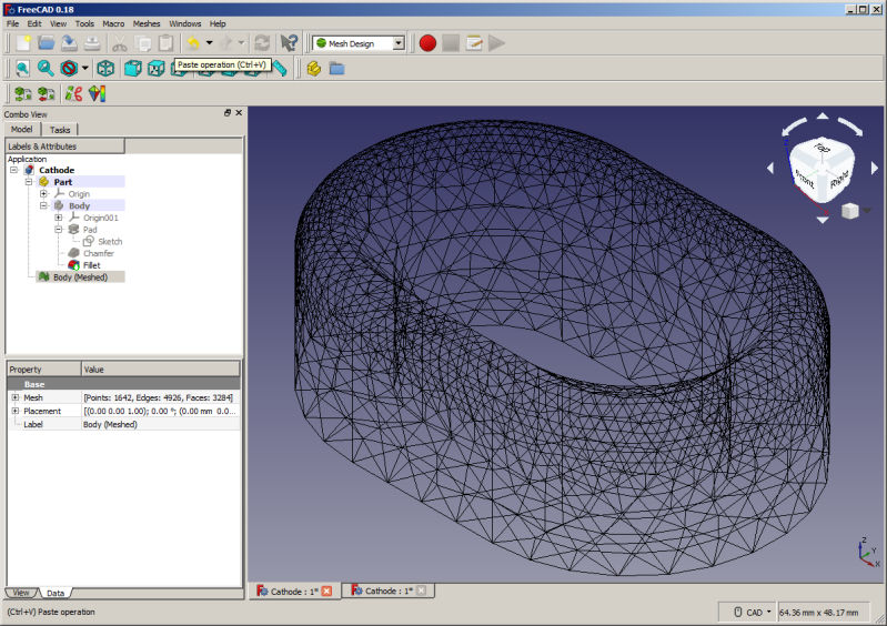
Figure 9. FreeCAD, mesh ready for export.
Because FreeCAD is the subject of this article, I will mention only briefly how to use the stereo-lithography file in MetaMesh. The downloadable file SheetGun.MIN illustrates several techniques:
- Loading Cathode.AST, shifting it in the solution space and fitting elements to the surface.
- Combining the STL model with a standard MetaMesh shape (an extrusion) to create a emission surface within the focusing electrode (the part named EMITTER).
- I defined another FreeCAD model to represent the anode and flipped it around for the proper orientation in the solution space.
- The COAT command was used in the EMITTER specification to create a set of nodes to define emission facets for an OmniTrak solution.
Figure 10 shows the result. In conclusion, FreeCAD provides a path to design precision 3D objects of any shape with a moderate amount of work. The program creates good quality STL meshes that can be imported reliably by MetaMesh.
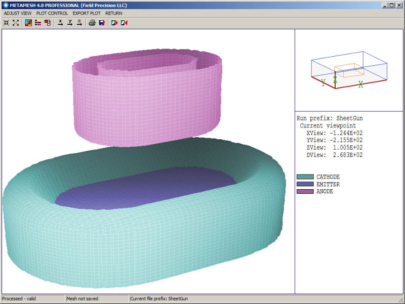
Figure 10. MetaMesh, assembly using the FreeCAD part.
LINKS
