We were recently contacted by a Trak user who encountered an error of the type Could not locate emission surface. He had modified an existing solution involving space-charge-limited emission, replacing a flat emitter with a convex surface. The problem and its solution illustrate some useful techniques in Trak and Mesh.
First, the problem. Figure 1 shows a magnified view of the edge of the cathode. The violet elements represent the metal electrode (fixed potential) and the green elements represent vacuum. The emission surface is a set of nodes painted on the convex surface of the cathode. In his Mesh file, the user employed the same arc vector specifications for both the cathode section and the emission surface. In this case, the emission nodes extended to the surface discontinuity (red arrow). I was able to confirm this by switching between element (first picture) and node (second picture) views in Mesh. The problem was that when Trak tried to project an emission surface from the facet adjacent to the discontinuity, the resulting points were inside the fixed-potential region rather than vacuum, hence the error message.
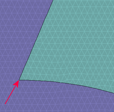
Figure 1. Element view of the emission surface.
There was no need to extend the emission surface into the indentation. The electric field there is low and the emitted current would made a negligible contribution to the beam. The solution would be accurate if the emission surface stopped at the node indicated by the red arrow in Figure 2. For a choice DEmit equal to 1.5 element widths, all projected points from the remaining surface facets would be in the vacuum region, eliminating the error.
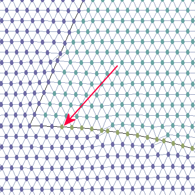
Figure 2. Node view of the reduced emission surface.
The question is how to shorten the arc vector of the emission surface without mathematical drudgery. I was able to regenerate the arc quickly using two techniques:
- I used endpoint coordinates that Mesh had already calculated.
- I modified the MIN file directly with a text editor.
To begin, I turned off Snap mode in Mesh so I could zoom into a small region near the indentation. Next, I activated Node display mode to produce a view like that of the second figure. The coordinates of each node of the emission surface were set to lie exactly on the arc of the cathode surface. I picked the Node information command, moved the cursor close to the node indicated by the red arrow and clicked the left button. Mesh highlighted the node and displayed its exact coordinates: z = 8.2305, r = 3.2479. I then opened the MIN file with an editor and located the emission surface region. I changed this arc:
A 9.7240 1.6760 8.1500 3.2500 8.1500 1.6760
to this one:
A 9.7240 1.6760 8.2305 3.2479 8.1500 1.6760
Mesh processed the revised file with no problem, creating the node distribution in the second picture (the emission surface nodes with the new arc are show in yellow).
In general, this method of shortening an arc or line vector is much quicker than going back to the Mesh drawing editor or a CAD program. Furthermore, the new node coordinates are at a position where Mesh originally wanted to set a node, so the method is less likely to produce an error or distorted element. Note that the new arc vector will appear in the Mesh drawing editor if you graphically edit the revised MIN file.
LINKS
