Edges of electrodes are a pitfall in finite-element calculations. We have a natural inclination toward crisp edges that look good in plots. The issue is how much are we willing to pay for those edges in a field solution if they contribute nothing to the accuracy of the results.
The top example in the first figure shows a three-dimensional mesh representation of a cylinder generated by MetaMesh. Although the curved side is close to ideal, the code has made some compromises on the sharp edge where the side meets the top. The result is the best fit consistent with the chosen element size. It is possible to improve the appearance of the edge by using smaller elements or forcing the nodes closer to the circular boundary (edge fitting). There are two penalties: 1) the solution time would be significantly longer and 2) there is an increased chance of element distortion. The critical question is whether there are significant benefits to offset the penalties.
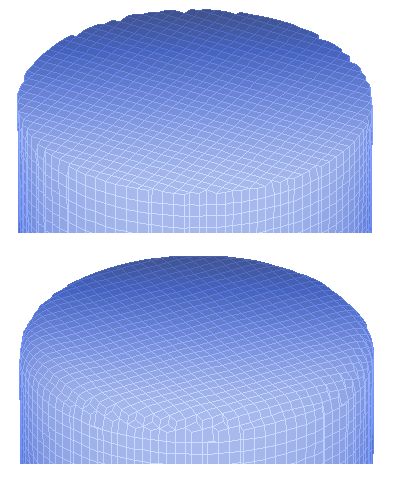
MetaMesh resolutions, sharp and filleted edges.
The nature of the Poisson equation is to seek the smoothest possible variation of electrostatic potential over a volume. At a sharp electrode edge, equipotential lines are required to make an abrupt bend, implying an effectively infinite local electrode field. Because such a field is impossible, all edges in nature have a radius (although it might be too small to see). Small edge radii give large (but finite) fields.
In a numerical calculation, the element defines the limit of spatial resolution. Local field values are invalid near features that are smaller than the surrounding elements. The left-most entry in Fig. 2 shows an electrostatic solution near an electrode edge that has a radius much smaller than the element size (the colors show the average electric field in the elements). An interpolation to the electrode point would give a large but effective meaningless value for |E|. Reducing the element size (as in the middle case) improves the field distribution at locations one or more elements away from the edge, but simply gives a different meaningless value for |E| at the electrode surface. The third case a better method to find the surface field on an electrode. In this case, the tip is represented by a reasonable radius of curvature that extends over several elements. Here, field interpolations will give accurate value of |E| at all positions on the surface.
When you find yourself forcing a numerical code to conform to your desires, the code is often trying to tell you something. In this example, MetaMesh was upset that I was using sharp edges in a high-voltage system. When I put a radius on the cylinder edge (as in the second case of the first figure), the code breathed a sigh of relief and proceeded about its duties, producing a nice fit. To conclude, I want to emphasize that I am not implying that you have to put radii on all parts in an electrostatic calculation. If the electrode surface is removed from the volume of interest (such as a beam line) and you don't care about the exact field levels on the electrode surface, sharp edges have little effect on the solution accuracy in critical regions.
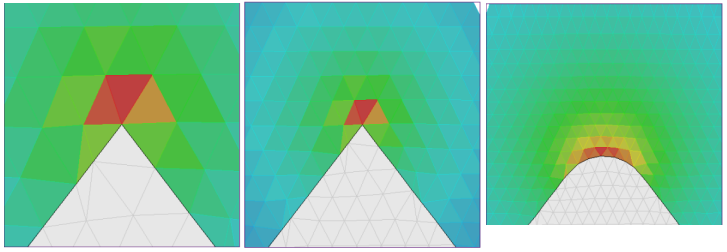
Figure 2. Electric field magnitude near an electrode tip.
LINKS
