High-current electron-beam guns typically have the geometry of Fig. 1. The flat or concave cathode operates in the space-charge limited mode. A shaped focusing electrode compensates for the effect of beam-generated electric fields to generate a parallel or converging beam. The heated cathode is composed of a high-temperature material like tungsten. The focusing electrode is composed of a more easily-machined material like molybdenum. The narrow gap between the components prevents conductive heat loss and melting of the focusing electrode.
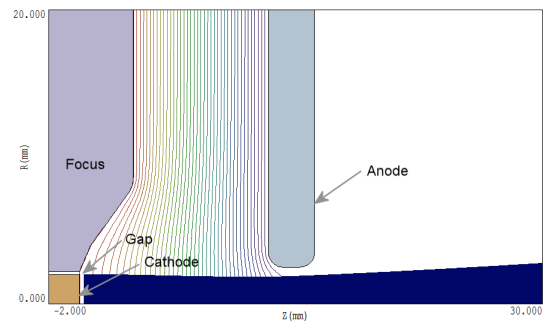
Figure 1. Two-dimensional Trak model of a high-current electron-beam gun.
It is relatively easy to set a narrow gap in a two-dimensional Trak mesh. The task is more challenging for three-dimensional OmniTrak meshes, where large numbers of elements lead to long run times. One purpose of this article is to demonstrate how to a create a cathode surface with good facets by optimizing the fitting logic for parts of the cathode assembly. A second activity is to confirm that Trak and OmniTrak generate almost identical results for a test geometry.
The benchmark electron gun of Fig. 1 has a flat cathode with 2.0 mm radius. The applied voltage on the cathode and focusing electrode is -54 kV. The focusing electrode shape gives some beam convergence in the acceleration gap and a modest divergence after passing through the extraction aperture. The combined effects of the focusing electrode profile and the 0.2 mm gap give a beam with good current-density uniformity and low emittance. A Trak calculation gives current density je = 16.4 ± 0.8 A/cm? at the cathode and total current 2.062 A. The top plot in Fig. 2 shows the phase-space distribution (r, r') at z = 30.0 mm. Over-focusing at the edge is relatively small.
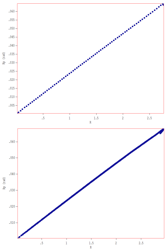
Figure 2. Phase-space distributions (r,r') for the extracted beam at z = 30.0 mm.
To minimize run time in OmniTrak, the calculation is performed in the first quadrant of the x-y plane (x ≥ 0.0 mm, y ≥ 0.0 mm) with symmetry boundaries at x = 0.0 mm and y = 0.0 mm for both the fields and electron trajectories. The element sizes near the emission surface have the same dimensions as those in the Trak calculation (Δx = Δy = 0.050 mm, Δz = 0.125 mm). The mesh had 1.63 million elements. Figure 3 shows a slice view of the mesh geometry near the cathode surface.
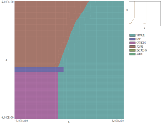
Figure 3. Detail of the mesh for the OmniTrak calculation in the plane y = 0.0 mm.
The cathode assembly is formed from three parts:
- A turning to represent the cathode, with outline specifications taken from the Trak input file. The part is associated with the CATHODE region (fixed potential equal to -54 kV) in the HiPhi and OmniTrak calculations.
- A turning to represent the focusing electrode, again with outline vectors from the Trak input file (FOCUS region with -54 kV fixed potential).
- A turning to represent the gap, with inner radius 2.0 mm and outer radius 2.2 mm. As shown, the shape extends a few elements past the cathode surface. The part is assigned to the GAP region, which has the same physical properties in the electrostatic calculation as the VACUUM region (εr = 1.0).
I employed two techniques to ensure that the facets on the cathode surface were flat and well-formed. The first is simple: pick a foundation mesh that minimizes the work that MetaMesh must perform. In this case, I made sure that a foundation element boundary occurred at z = 0.0 mm, the position of the cathode surface. Here is the complete mesh specification in z:
ZMesh
-2.00 -0.25 0.250
-0.25  0.50 0.125
 0.50 30.00 0.250
End
If the element boundary were at an arbitrary position (z ≠ 0.0 mm), then it would be necessary for MetaMesh to perform thousands of needless operations to shift facets.
The second technique is to plan fitting operations carefully. Fitting of a part is controlled by the commands:
SURFACE REGION RegNo
SURFACE PART PartNo
In response to the first command, MetaMesh collects all facets of the part that are shared with elements that have region number RegNo. The program them shifts the facet nodes toward the theoretical outer surface of the part. The second command form has similar function, except that MetaMesh picks facets adjacent to elements with part number PartNo.
Let's consider how fitting works for the cathode assembly. Here is a summary of fitting commands for the contiguous parts of the cathode assembly:
PART
  Region: Gap
  Name: Gap
  Surface Region Cathode
  Surface Region Focus
END
PART
  Region: Cathode
  Name: Cathode
  Coat Vacuum Emission
END
PART
  Region: Focus
  Name: Focus
  Surface Region Vacuum
END
To begin, note the order of parts. The dielectric part appears before parts with fixed potential. With this order, any shared nodes are assigned the region number of the CATHODE or FOCUS parts, giving the correct fixed-potential condition on the electrode surfaces.
I will point out some features of the fitting list and then explain how they work. The GAP part has its own region assignment and contains commands for fitting to both the CATHODE and FOCUS. The CATHODE part has no SURFACE command, while the FOCUS part has a single command for surfaces in contact with elements of the VACUUM region. The order is chosen to ensure that facets on the front and side faces of the cathode are shifted only in the x-y plane, not in z. Here is the logic:
- Fitting parts with sharp edges (like a cylinder or the annular shape of the GAP) involves ambiguity. Should the facet be moved toward one edge or the other? This is the reason why I extended the GAP past the CATHODE and FOCUS. The end is far enough away to ensure that MetaMesh moves facets to the inner and outer cylindrical surfaces when fitting the GAP. In other words, node displacements are purely in the x-y plane.
- There are two reasons why there is no SURFACE command for the CATHODE: 1) nodes on the front surface already lie at z = 0.0 and 2) the side surfaces have already been positioned through fitting of the GAP.
- The inner surface of the FOCUS has already been set by fitting of the GAP. The single SURFACE command specifies that front-surface facets (adjacent to VACUUM elements) should be adjusted. The GAP was defined as a separate region to ensure that only nodes on front surface facets are moved.
- The COAT command for the CATHODE resets the region number of the nodes of facets adjacent to VACUUM elements. The new region number has the emission property in OmniTrak. Because the GAP has its own region number, only facets on the front face of the CATHODE are set as emitters.
Figure 4 is a three-dimensional view of the completed cathode assembly. Facets on the front cathode face are flat and well-formed. The OmniTrak calculation gives a quadrant current of 0.512 A, corresponding to a total current 2.046 A. The bottom plot of Fig. 2 shows the phase-space distribution at z = 30.0 mm for 5024 model electrons. A comparison at this distance provides a sensitive test of correspondence. The distributions are almost identical. The beam is slightly larger in the OmniTrak calculation.
Program users can use this link to download input files for the calculations:
cathodegapdemo.zip
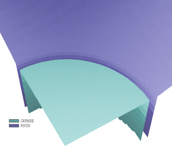
Figure 4. Three-dimensional view of the completed cathode and focus electrode..
LINKS
